103 www.national.com
CP3BT26
receive the next packet. The erroneous
packet is ignored and not transferred via
DMA. If this bit is cleared, automatic error
handling ceases.
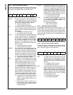
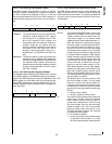
18.3.24 Endpoint Control 0 Register (EPC0)
The EPC0 register controls the mandatory Endpoint 0. It is
clear after reset. Reserved bits read undefined data.
EP The Endpoint Address field holds the 4-bit
endpoint address. For Endpoint 0, these bits
are hardwired to 0000b. Writing a 1 to any of
the EP bits is ignored.
DEF The Default Address aids in the transition
from the default address to the assigned ad-
dress. When set, the device responds to the
default address without regard to the contents
of FAR6-0/EP03-0 fields. When an IN packet
is transmitted for the endpoint, the DEF bit is
automatically cleared. This bit provides read/
write access from the CPU bus. After reset,
this bit is clear. The transition from the default
address 00000000000b to an address as-
signed during bus enumeration may not occur
in the middle of the SET_ADDRESS control
sequence. This is necessary to complete the
control sequence. However, the address must
change immediately after this sequence fin-
ishes in order to avoid errors when another
control sequence immediately follows the
SET_ADDRESS command. On USB reset,
software has 10 ms for set-up, and should
write 80h to the FAR register and 00h to the
EPC0 register. On receipt of a
SET_ADDRESS command, software must
write 40h to the EPC0 register and 80h to the
FAR register. It must then queue a zero length
IN packet to complete the status phase of the
SET_ADDRESS control sequence.
0 – Do not respond to the default address.
1 – Respond to default address.
STALL The Stall bit can be used to enable STALL
handshakes under the following conditions:
The transmit FIFO is enabled and an IN
token is received.
The receive FIFO is enabled and an OUT
token is received.
A SETUP token does not cause a STALL
handshake to be generated when this bit is
set. After transmitting the STALL handshake,
the RX_LAST and the TX_DONE bits in the
respective Receive/Transmit Status registers
are set. This bit allows read/write access from
the CPU bus. After reset this bit is cleared.
0 – Disable STALL handshakes.
1 – Enable STALL handshakes.
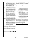
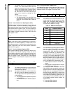
18.3.25 Transmit Status 0 Register (TXS0)
The TXS0 register reports the transmit status of the manda-
tory Endpoint 0. It is loaded with 08h after reset. This regis-
ter allows read-only access from the CPU bus.
TCOUNT The Transmission Count field indicates the
number of empty bytes available in the FIFO.
This field is never larger than 8 for Endpoint 0.
TX_DONE The Transmission Done bit indicates whether
a packet has completed transmission. The
TX_DONE bit is cleared when this register is
read.
0 – No completion of packet transmission has
occurred.
1 – A packet has completed transmission.
ACK_STAT The Acknowledge Status bit indicates the sta-
tus, as received from the host, of the ACK for
the packet previously sent. This bit is to be in-
terpreted when TX_DONE is set. It is set
when an ACK is received; otherwise, it re-
mains cleared. This bit is cleared when this
register is read.
0 – No ACK received.
1 – ACK received.
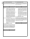
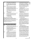
18.3.26 Transmit Command 0 Register (TXC0)
The TXC0 register controls the mandatory Endpoint 0 when
used in transmit direction. This register allows read/write ac-
cess from the CPU bus. It is clear after reset. Reading re-
served bits returns undefined data.
TX_EN The Transmission Enable bit enables data
transmission from the FIFO. It is cleared by
hardware after transmitting a single packet, or
a STALL handshake, in response to an IN to-
ken. It must be set by software to start packet
transmission. The RX_EN bit in the Receive
Command 0 (RXC0) register takes prece-
dence over this bit; i.e. if the RX_EN bit is set,
the TX_EN bit is ignored until RX_EN is reset.
Zero length packets are indicated by setting
this bit without writing any data to the FIFO.
0 – Transmission from the FIFO disabled.
1 – Transmission from the FIFO enabled.
TOGGLE The Toggle bit specifies the PID used when
transmitting the packet. A value of 0 causes a
DATA0 PID to be generated, while a value of 1
causes a DATA1 PID to be generated. This bit
is not altered by the hardware.
0 – DATA0 PID is used.
1 – DATA1 PID is used.
7 6 5 4 3 0
STALL DEF Reserved EP
7 6 5 4 3 0
Res. ACK_STAT TX_DONE Res. TCOUNT
7 5 4 3 2 1 0
Reserved IGN_IN FLUSH TOGGLE Res. TX_EN


