www.national.com 204
CP3BT26
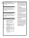
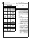
26.5.5 Reload/Capture A Register (TCRA)
The TCRA register is a word-wide, read/write register that
holds the reload or capture value for Timer/Counter 1. The
register contents are not affected by a reset and are un-
known after power-up.
26.5.6 Reload/Capture B Register (TCRB)
The TCRB register is a word-wide, read/write register that
holds the reload or capture value for Timer/Counter 2. The
register contents are not affected by a reset and are un-
known after power-up.
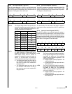
26.5.7 Timer Mode Control Register (TCTRL)
The TCTRL register is a byte-wide, read/write register that
sets the operating mode of the timer/counter and the TA and
TB pins. This register is cleared at reset. The register format
is shown below.
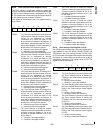
MDSEL The Mode Select field sets the operating
mode of the timer/counter as follows:
00 – Mode 1: PWM plus system timer.
01 – Mode 2: Dual-Input Capture plus system
timer.
10 – Mode 3: Dual Timer/Counter.
11 – Mode 4: Single-Input Capture and Sin-
gle Timer.
TAEDG The TA Edge Polarity bit selects the polarity of
the edges that trigger the TA input.
0 – TA input is sensitive to falling edges (high
to low transitions).
1 – TA input is sensitive to rising edges (low
to high transitions).
TBEDG The TB Edge Polarity bit selects the polarity of
the edges that trigger the TB input. In pulse-
accumulate mode, when this bit is set, the
counter is enabled only when TB is high;
when this bit is clear, the counter is enabled
only when TB is low.
0 – TB input is sensitive to falling edges (high
to low transitions).
1 – TB input is sensitive to rising edges (low
to high transitions).
TAEN The TA Enable bit controls whether the TA pin
is enabled to operate as a preset input or as a
PWM output, depending on the timer operat-
ing mode. In Mode 2 (Dual Input Capture), a
transition on the TA pin presets the TCNT1
counter to FFFFh. In the other modes, TA
functions as a PWM output. When this bit is
clear, operation of the pin for the timer/counter
is disabled.
0 – TA input disabled.
1 – TA input enabled.
TBEN The TB Enable bit controls whether the TB pin
in enabled to operate in Mode 2 (Dual Input
Capture) or Mode 4 (Single Input Capture and
Single Timer). A transition on the TB pin pre-
sets the corresponding timer/counter to
FFFFh (TCNT1 in Mode 2 or TCNT2 in Mode
4). When this bit is clear, operation of the pin
for the timer/counter is disabled. This bit set-
ting has no effect in Mode 1 or Mode 3.
0 – TB input disabled.
1 – TB input enabled.
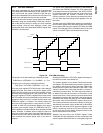
TAOUT The TA Output Data bit indicates the current
state of the TA pin when the pin is used as a
PWM output. The hardware sets and clears
this bit, but software can also read or write this
bit at any time and therefore control the state
of the output pin. In case of conflict, a software
write has precedence over a hardware up-
date. This bit setting has no effect when the
TA pin is used as an input.
0 – TA pin is low.
1 – TA pin is high.
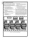
TEN The Timer Enable bit controls whether the
Multi-Function Timer is enabled. When the
module is disabled all clocks to the counter
unit are stopped to minimize power consump-
tion. For that reason, the timer/counter regis-
ters (TCNT1 and TCNT2), the capture/reload
registers (TCRA and TCRB), and the interrupt
pending bits (TXPND) cannot be written in
this mode. Also, the 5-bit clock prescaler and
the interrupt pending bits are cleared, and the
TA I/O pin becomes an input.
0 – Multi-Function Timer is disabled.
1 – Multi-Function Timer is enabled.
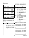
15 0
TCRA
15 0
TCRB
7 6 5 4 3 2 1 0
TEN TAOUT TBEN TAEN TBEDG TAEDG MDSEL


