175 www.national.com
CP3BT26
23.0 Microwire/SPI Interface
Microwire/Plus is a synchronous serial communications
protocol, originally implemented in National Semiconduc-
tor's COP8
®
and HPC families of microcontrollers to mini-
mize the number of connections, and therefore the cost, of
communicating with peripherals.
The CP3BT26 has an enhanced Microwire/SPI interface
module (MWSPI) that can communicate with all peripherals
that conform to Microwire or Serial Peripheral Interface
(SPI) specifications. This enhanced Microwire interface is
capable of operating as either a master or slave and in 8- or
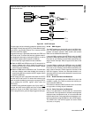
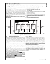
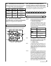
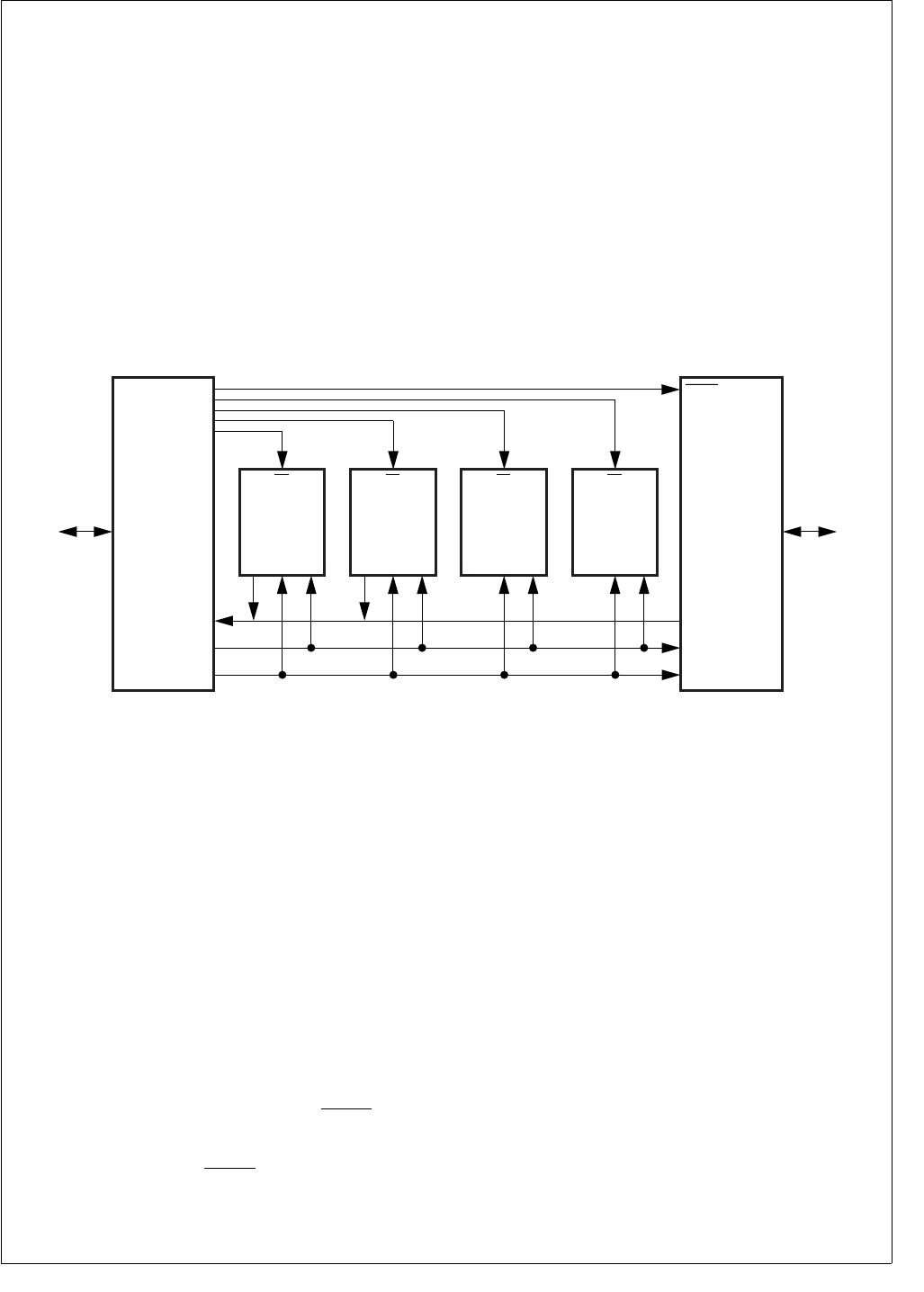
16-bit mode. Figure 83 shows a typical enhanced Microwire
interface application.
The enhanced Microwire interface module includes the fol-
lowing features:
Programmable operation as a Master or Slave
Programmable shift-clock frequency (master only)
Programmable 8- or 16-bit mode of operation
8- or 16-bit serial I/O data shift register
Two modes of clocking data
Serial clock can be low or high when idle
16-bit read buffer
Busy bit, Read Buffer Full bit, and Overrun bit for polling
and as interrupt sources
Supports multiple masters
Maximum bit rate of 12M bits/second (master mode) 6M
bits/second (slave mode) at 24 MHz System Clock
Supports very low-end slaves with the Slave Ready out-
put
Echo back enable/disable (Slave only)
Figure 83. Microwire Interface
23.1 MICROWIRE OPERATION
The Microwire interface allows several devices to be con-
nected on one three-wire system. At any given time, one of
these devices operates as the master while all other devices
operate as slaves. The Microwire interface allows the device
to operate either as a master or slave transferring 8- or 16-
bits of data.
The master device supplies the synchronous clock (MSK)
for the serial interface and initiates the data transfer. The
slave devices respond by sending (or receiving) the re-
quested data. Each slave device uses the master’s clock for
serially shifting data out (or in), while the master shifts the
data in (or out).
The three-wire system includes: the serial data in signal
(MDIDO for master mode, MDODI for slave mode), the se-
rial data out signal (MDODI for master mode, MDIDO for
slave mode), and the serial clock (MSK).
In slave mode, an optional fourth signal (MWCS
) may be
used to enable the slave transmit. At any given time, only
one slave can respond to the master. Each slave device has
its own chip select signal (MWCS
) for this purpose.
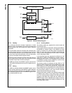
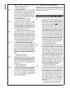
Figure 84 shows a block diagram of the enhanced Microwire
serial interface in the device.
23.1.1 Shifting
The Microwire interface is a full duplex transmitter/receiver.
A 16-bit shifter, which can be split into a low and high byte,
is used for both transmitting and receiving. In 8-bit mode,
only the lower 8-bits are used to transfer data. The transmit-
ted data is shifted out through MDODI pin (master mode) or
MDIDO pin (slave mode), starting with the most significant
bit. At the same time, the received data is shifted in through
MDIDO pin (master mode) or MDODI pin (slave mode), also
starting with the most significant bit first.
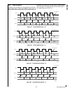
The shift in and shift out are controlled by the MSK clock. In
each clock cycle of MSK, one bit of data is transmitted/re-
ceived. The 16-bit shifter is accessible as the MWDAT reg-
ister. Reading the MWDAT register returns the value in the
read buffer. Writing to the MWDAT register updates the 16-
bit shifter.
MDIDO MDIDO
MDODI
I/O
Lines
I/O
Lines
MDODI
MSK
MSK
Master
8-Bit
A/D
Slave
GPIO
CS
DO SK DI
MWCS
1K Bit
EEPROM
CS
DO SK DI
LCD
Display
Driver
CS
SK DI
VF
Display
Driver
CS
SK DI
DS067


