


146
The aim of the Main Units (such as P2-UMT1664“M”) and Stacking Units
(such as P2-UMT1664“S”) is to allow users to build the Paragon system
to include additional channel ports and the tiers up to three levels, so that
more users and channels can be configured to control more servers. The
system does not need to be over-redundant in accessibility, but
administrators should consider the configurations illustrated in this
chapter. In more complex stacked Paragon setups, there are important
guidelines about legal and illegal device configurations that must be
followed to ensure functionality.
In This Chapter
Principles of Re-Connection..................................................................146
Tiered Configurations ............................................................................147
Stac
ked Configurations .........................................................................
155
Loop-Back Configuration.......................................................................159
Different Cabl
e Length Configuration....................................................
160
P2-HubPac Configuration and Multiple Video.......................................161
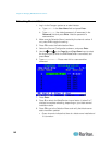
Principles of Re-Connection
When a change is made to a connected tiered device, we recommended
that power to all devices is recycled, if possible. This includes the device
where the connection is changed directly, as well as all devices below it
in the system architecture.
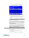
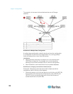
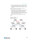
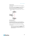
The sequence of power recycling should start from the HIGHEST tiered
device and end with the Base Unit (first-tier Paragon switch). For
example, in a “Single Base” configuration (only one Paragon switch as
the Base Unit), if a connection change is made at a device on the third
tier, the sequence of power recycling should be as follows:
The third-tier device with the changed connection
The second-tier device connected to the third-tier device
The Base Unit
Chapter 10
Configurations