


Chapter 3: Rackmount and Installation
34
a. Connect a CIM to a server—see Specifications (on page 185)
for specific instructions on connecting different CIM types to a
server.
b. Plug one end of a Cat5 UTP cable into the RJ45 port on a CIM.
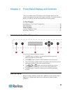
c. Plug the other end of cable into the RJ45 1-IN port on the back
of HubPac.
d. Turn ON the server.
e. Repeat the above steps to connect the remaining servers,
connecting the Cat5 UTP cable to the HubPac at the RJ45 2-IN,
3-IN, 4-IN, 5-IN, 6-IN, 7-IN, and 8-IN port for each consecutive
server (2 through 8) added.
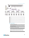
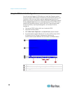
3. Connect the HubPac to each Paragon switch by repeating all of the
following steps for each 5-port cluster on the HubPac:
Note: There are 8 five-port clusters on the HubPac. For each cluster
the number in front of the RJ45 IN port represents the cluster
number. For example, cluster 1’s first RJ45 port is 1 IN, cluster 2’s is
2 IN, and so on. In the instructions below, “X” represents the cluster
number (1 through 8).
a. Plug one end of a Cat5 UTP cable into the RJ45 X-1 port on the
back of the HubPac.
b. Plug the other end of the cable into channel port # N on the back
of one of the desired Paragon switches.
c. Plug one end of a Cat5 UTP cable into the RJ45 X-2 port on the
back of the HubPac.
d. Plug the other end of the cable into channel port # N on the back
of the second desired Paragon switch.
e. Plug one end of a Cat5 UTP cable into the RJ45 X-3 port on the
back of the HubPac.
f. Plug the other end of the cable into channel port # N on the back
of the third desired Paragon switch.
g. Plug one end of a Cat5 UTP cable into the RJ45 X-4 port on the
back of the HubPac.
h. Plug the other end of the cable into channel port # N on the back
of the fourth desired Paragon switch.
4. Connect the power cord to the back of the HubPac. Turn ON the
HubPac.
5. Turn ON each of the Paragon switches.