


Flash Memory Operation
5-8 Flash Memory Controller
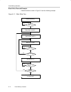
5.3.3 Writing Flash Memory
The write modes, selected by the WRT and BLKWRT bits, are listed in
Table 5−1. Interrupts are automatically disabled during a flash write and
re-enabled after the write. Any interrupt that occurred during the write will have
its associated flag set, and will generate an interrupt request when re-enabled.
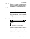
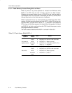
Table 5−2.Write Modes
BLKWRT WRT
Write Mode
0 1 Byte/word write
1 1 Block write
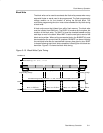
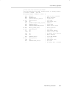
Both write modes use a sequence of individual write instructions, but using the
block write mode is approximately twice as fast as byte/word mode, because
the voltage generator remains on for the complete block write. Any instruction
that modifies a destination can be used to modify a flash location in either
byte/word write mode or block write mode.
The BUSY bit is set while a write operation is active and cleared when the
operation completes. If the write operation is initiated from RAM, the CPU must
not access flash while BUSY=1. Otherwise, an access violation occurs,
ACCVIFG is set, and the flash write is unpredictable.
Byte/Word Write
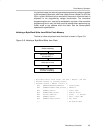
A byte/word write operation can be initiated from within flash memory or from
RAM. When initiating from within flash memory, all timing is controlled by the
flash controller, and the CPU is held while the write completes. After the write
completes, the CPU resumes code execution with the instruction following the
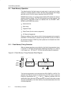
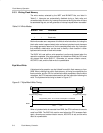
write. The byte/word write timing is shown in Figure 5−7.
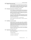
Figure 5−7. Byte/Word Write Timing
BUSY
Programming Operation Active
Programming Time, V
CC
Current Consumption is Increased
t
Word
= 35/f
FTG
Generate
Programming Voltage
Remove
Programming Voltage
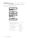
When a byte/word write is executed from RAM, the CPU continues to execute
code from RAM. The BUSY bit must be zero before the CPU accesses flash
again, otherwise an access violation occurs, ACCVIFG is set, and the write
result is unpredictable.