


Timer_A Operation
12-16 Timer_A
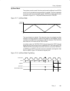
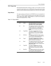
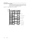
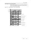
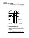
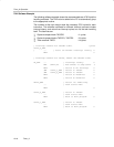
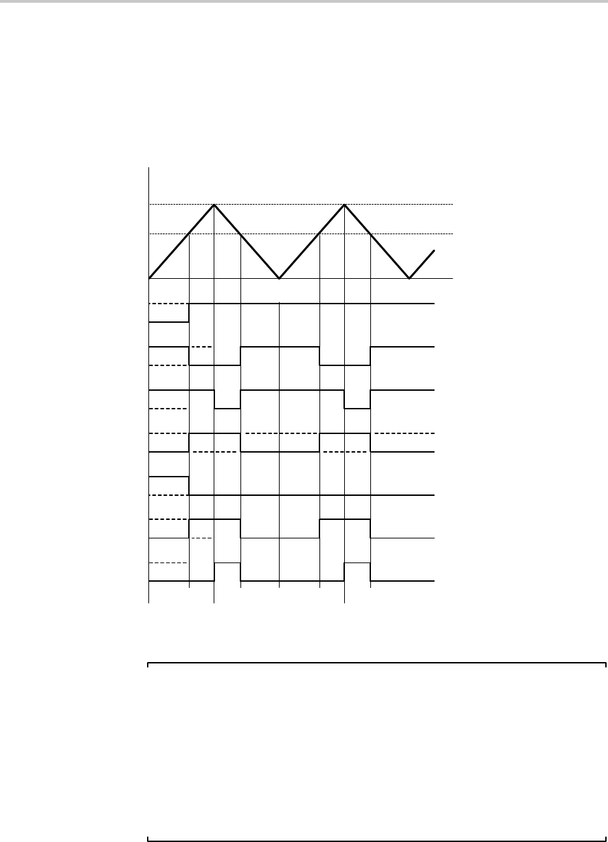
Output Example—Timer in Up/Down Mode
The OUTx signal changes when the timer equals TACCRx in either count
direction and when the timer equals TACCR0, depending on the output mode.
An example is shown in Figure 12−14 using TACCR0 and TACCR2.
Figure 12−14. Output Example—Timer in Up/Down Mode
0h
0FFFFh
TAIFG
Output Mode 1: Set
Output Mode 2: Toggle/Reset
Output Mode 3: Set/Reset
Output Mode 4: Toggle
Output Mode 5: Reset
Output Mode 6: Toggle/Set
Output Mode 7: Reset/Set
TACCR0
TACCR2
EQU2
TAIFG
Interrupt Events
EQU2
EQU0
EQU2 EQU2
EQU0
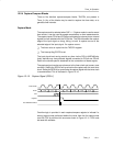
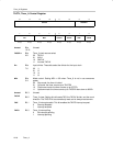
Note: Switching Between Output Modes
When switching between output modes, one of the OUTMODx bits should
remain set during the transition, unless switching to mode 0. Otherwise,
output glitching can occur because a NOR gate decodes output mode 0. A
safe method for switching between output modes is to use output mode 7 as
a transition state:
BIS #OUTMOD_7,&TACCTLx ; Set output mode=7
BIC #OUTMODx,&TACCTLx ; Clear unwanted bits