USART Operation: UART Mode
14-14 USART Peripheral Interface, UART Mode
Receive Bit Timing
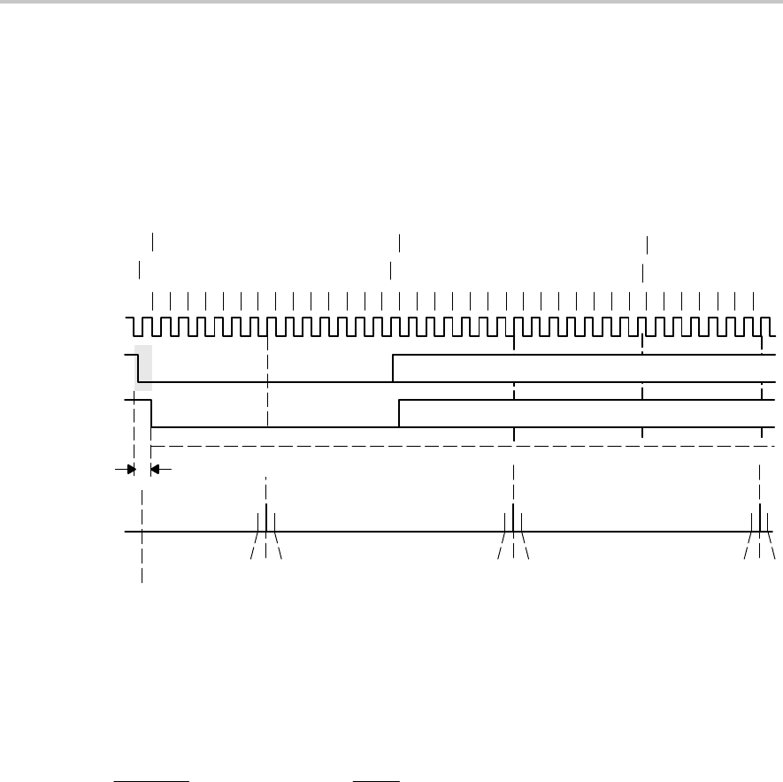
Receive timing consists of two error sources. The first is the bit-to-bit timing
error. The second is the error between a start edge occurring and the start
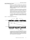
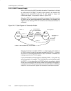
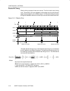
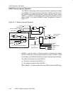
edge being accepted by the USART. Figure 14−9 shows the asynchronous
timing errors between data on the URXDx pin and the internal baud-rate clock.
Figure 14−9. Receive Error
123456
0
i
t
0
t
ideal
78
1
t
1
2
9 10 11 12 13 14 1 2 3 4 5 6 7 8 9 10 11 1213 14 1 2 3 4 5 6 7
t
0
t
1
t
2
ST D0 D1
D0 D1
ST
Synchronization Error ± 0.5x BRCLK
Int(UxBR/2)+m0 =
Int (13/2)+1 = 6+1 = 7
Majority Vote Taken Majority Vote Taken
UxBR +m1 = 13+1 = 14 UxBR +m2 = 13+0 = 13
Majority Vote Taken
BRCLK
URXDx
URXDS
t
actual
Sample
URXDS
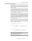
The ideal start bit timing t
ideal(0)
is half the baud-rate timing t
baud
rate
because
the bit is tested in the middle of its period. The ideal baud rate timing t
ideal(i)
for
the remaining character bits is the baud rate timing t
baud
rate
. The individual bit
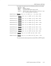
errors can be calculated by:
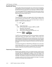
Error [%] +
ȧ
ȡ
Ȣ
baud rate
BRCLK
NJ
2
ƪ
m0 ) int
ǒ
UxBR
2
Ǔ
ƫ
)
ǒ
i UxBR ) S
j
i+1
m
i
Ǔ
Nj
* 1 * j
Ǔ
100%
Where:
baud rate is the required baud rate
BRCLK is the input frequency—selected for UCLK, ACLK, or SMCLK
j = 0 for the start bit, 1 for data bit D0, and so on
UxBR is the division factor in registers UxBR1 and UxBR0


