


USART Operation: SPI Mode
15-6 USART Peripheral Interface, SPI Mode
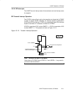
15.2.3 Slave Mode
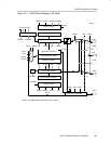
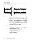
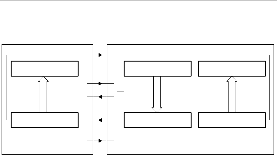
Figure 15−3. USART Slave and External Master
Receive Buffer UxRXBUF
Receive Shift Register
LSB
MSB
Transmit Buffer UxTXBUF
Transmit Shift Register
LSB
MSB
SPI Receive Buffer
Data Shift Register DSR
LSB
MSB
SOMISOMI
SIMOSIMO
MASTER SLAVE
Px.x STE
STE
SS
Port.x
UCLK
SCLK
MSP430 USARTCOMMON SPI
Figure 15−3 shows the USART as a slave in both 3-pin and 4-pin
configurations. UCLK is used as the input for the SPI clock and must be
supplied by the external master. The data-transfer rate is determined by this
clock and not by the internal baud rate generator. Data written to UxTXBUF
and moved to the TX shift register before the start of UCLK is transmitted on
SOMI. Data on SIMO is shifted into the receive shift register on the opposite
edge of UCLK and moved to UxRXBUF when the set number of bits are
received. When data is moved from the RX shift register to UxRXBUF, the
URXIFGx interrupt flag is set, indicating that data has been received. The
overrun error bit, OE, is set when the previously received data is not read from
UxRXBUF before new data is moved to UxRXBUF.
Four-Pin SPI Slave Mode
In 4-pin slave mode, STE is used by the slave to enable the transmit and
receive operations and is provided by the SPI master. When STE is low, the
slave operates normally. When STE is high:
- Any receive operation in progress on SIMO is halted
- SOMI is set to the input direction
A high STE signal does not reset the USART module. The STE input signal
is not used in 3-pin slave mode.