


Flash Memory Operation
5-9 Flash Memory Controller
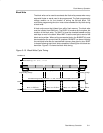
In byte/word mode, the internally-generated programming voltage is applied
to the complete 64-byte block, each time a byte or word is written, for 32 of the
35 f
FTG
cycles. With each byte or word write, the amount of time the block is
subjected to the programming voltage accumulates. The cumulative
programming time, t
CPT,
must not be exceeded for any block. If the cumulative
programming time is met, the block must be erased before performing any
further writes to any address within the block. See the device-specific
datasheet for specifications.
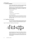
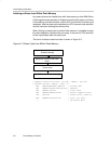
Initiating a Byte/Word Write from Within Flash Memory
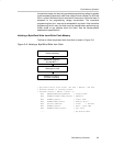
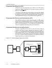
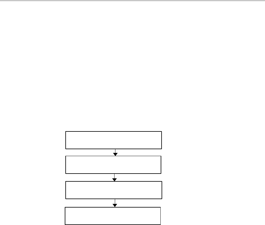
The flow to initiate a byte/word write from flash is shown in Figure 5−8.
Figure 5−8. Initiating a Byte/Word Write from Flash
Setup flash controller
and set WRT=1
Disable watchdog
Set WRT=0, LOCK=1,
re-enable watchdog
Write byte or word
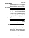
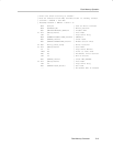
; Byte/word write from flash. 514 kHz < SMCLK < 952 kHz
; Assumes 0FF1Eh is already erased
; Assumes ACCVIE = NMIIE = OFIE = 0.
MOV #WDTPW+WDTHOLD,&WDTCTL ; Disable WDT
MOV #FWKEY+FSSEL1+FN0,&FCTL2 ; SMCLK/2
MOV #FWKEY,&FCTL3 ; Clear LOCK
MOV #FWKEY+WRT,&FCTL1 ; Enable write
MOV #0123h,&0FF1Eh ; 0123h −> 0FF1Eh
MOV #FWKEY,&FCTL1 ; Done. Clear WRT
MOV #FWKEY+LOCK,&FCTL3 ; Set LOCK
... ; Re-enable WDT?