


Scan IF Operation
24-13Scan IF
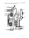
Internal Signal Connections to Timer1_A5
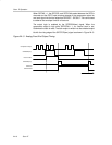
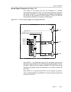
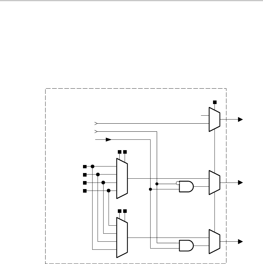
The outputs of the analog front end are connected to 3 different
capture/compare registers of Timer1_A5. The output stage of the analog front
end, shown in Figure 24−7. provides two different modes that are selected by
the SIFCS bit and provides the SIFOx signals to Timer1_A5. See the
device-specific datasheet for connection of these signals.
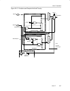
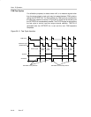
Figure 24−7. TimerA Output Stage of the Analog Front End
TimerA Output Stage
SIF0OUT
SIF1OUT
SIF2OUT
SIF3OUT
SIFS1x
SIFO0
SIFO1
SIFO2
SIFTESTS1(tsm)
SIFEX(tsm)
SIFCS
11
10
01
00
SIFS2x
11
10
01
00
1
0
1
0
1
00
Comparator Output
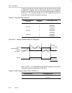
When SIFCS = 1, the SIFEX(tsm) signal and the comparator output can be
selected as inputs to different Timer1_A5 capture/compare registers. This can
be used to measure the time between excitation of a sensor and the last
oscillation that passes through the comparator or to perform a slope A/D
conversion.
When SIFCS =0, the output bits SIFxOUT can be selected as inputs to
Timer1_A5 with the SIFS1x and SIFS2x bits. This can be used to measure the
duty cycle of SIFxOUT.