LCD_A Controller Operation
19-7LCD_A Controller
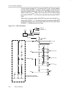
The internal bias generator supports 1/2 bias LCDs when LCD2B = 1, and 1/3
bias LCDs when LCD2B = 0 in 2-mux, 3-mux, and 4-mux modes. In static
mode the internal divider is disabled.
Some devices share the LCDCAP, R33, and R23 functions. In this case, the
charge pump cannot be used together with an external resistor divider with 1/3
biasing. When R03 is not available externally. The V5 is always AV
SS
.
LCD Contrast Control
The peak voltage of the output waveforms together with the selected mode
and biasing determine the contrast and the contrast ratio of the LCD. The LCD
contrast can be controlled in software by adjusting the LCD voltage generated
by the integrated charge pump using the VLCDx settings.
The contrast ratio depends on the used LCD display and the selected biasing
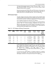
scheme. Table 19−1 shows the biasing configurations that apply to the
different modes together with the RMS voltages for the segments turned on
(V
RMS,ON
) and turned off (V
RMS,OFF
) as functions of V
LCD
. It also shows the
resulting contrast ratios between the on and off states.
Table 19−1.LCD Voltage and Biasing Characteristics
Mode Bias
Config.
LCDMx LCD2B
COM
Lines
Voltage
Levels
V
RMS,OFF
/V
LCD
V
RMS,ON
/
V
LCD
Contrast
Ratio
V
RMS,ON
/
V
RMS,OFF
static static 00 X 1 V1, V5 0 1 1/0
2−mux 1/2 01 1 2 V1, V3, V5 0.354 0.791 2.236
2−mux 1/3 01 0 2 V1, V2, V4, V5 0.333 0.745 2.236
3−mux 1/2 10 1 3 V1, V3, V5 0.408 0.707 1.732
3−mux 1/3 10 0 3 V1, V2, V4, V5 0.333 0.638 1.915
4−mux 1/2 11 1 4 V1, V3, V5 0.433 0.661 1.528
4−mux
1/3 11 0 4 V1, V2, V4, V5 0.333 0.577 1.732
A typical approach to determine the required V
LCD
is by equating V
RMS,OFF
with a defined LCD threshold voltage, typically when the LCD exhibits
approximately 10% contrast (V
th,10%
): V
RMS,OFF
= V
th,10%
. Using the values
for V
RMS,OFF
/V
LCD
provided in the table results in V
LCD
=
V
th,10%
/(V
RMS,OFF
/V
LCD
). In the static mode a suitable choice is V
LCD
greater
or equal than 3 times V
th,10%
.
In 3-mux and 4-mux mode typically a 1/3 biasing is used but a 1/2 biasing
scheme is also possible. The 1/2 bias reduces the contrast ratio but the
advantage is a reduction of the required full-scale LCD voltage V
LCD
.


