USART Operation: UART Mode
14-13USART Peripheral Interface, UART Mode
Transmit Bit Timing
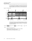
The timing for each character is the sum of the individual bit timings. By
modulating each bit, the cumulative bit error is reduced. The individual bit error
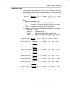
can be calculated by:
Error [%] +
NJ
baud rate
BRCLK
ƪ
(
j ) 1
)
UxBR ) S
j
i+0
m
i
ƫ
*
(
j ) 1
)
Nj
100%
With:
baud rate: Desired baud rate
BRCLK: Input frequency − UCLKI, ACLK, or SMCLK
j: Bit position - 0 for the start bit, 1 for data bit D0, and so on
UxBR: Division factor in registers UxBR1 and UxBR0
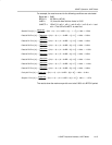
For example, the transmit errors for the following conditions are calculated:
Baud rate = 2400
BRCLK = 32,768 Hz (ACLK)
UxBR = 13, since the ideal division factor is 13.65
UxMCTL = 6Bh: m7=0, m6=1, m5=1, m4=0, m3=1, m2=0,
m1=1, and m0=1. The LSB of UxMCTL is used first.
Start bit Error [%] +
ǒ
baud rate
BRCLK
((
0 ) 1
)
UxBR ) 1
)
–1
Ǔ
100% + 2.54%
Data bit D0 Error [%] +
ǒ
baud rate
BRCLK
((
1 ) 1
)
UxBR ) 2
)
–2
Ǔ
100% + 5.08%
Data bit D1 Error [%] +
ǒ
baud rate
BRCLK
((
2 ) 1
)
UxBR ) 2
)
–3
Ǔ
100% + 0.29%
Data bit D2 Error [%] +
ǒ
baud rate
BRCLK
((
3 ) 1
)
UxBR ) 3
)
–4
Ǔ
100% + 2.83%
Data bit D3 Error [%] +
ǒ
baud rate
BRCLK
((
4 ) 1
)
UxBR ) 3
)
–5
Ǔ
100% +*1.95%
Data bit D4 Error [%] +
ǒ
baud rate
BRCLK
((
5 ) 1
)
UxBR ) 4
)
–6
Ǔ
100% + 0.59%
Data bit D5 Error [%] +
ǒ
baud rate
BRCLK
((
6 ) 1
)
UxBR ) 5
)
–7
Ǔ
100% + 3.13%
Data bit D6 Error [%] +
ǒ
baud rate
BRCLK
((
7 ) 1
)
UxBR ) 5
)
–8
Ǔ
100% +*1.66%
Data bit D7 Error [%] +
ǒ
baud rate
BRCLK
((
8 ) 1
)
UxBR ) 6
)
–9
Ǔ
100% + 0.88%
Parity bit Error [%] +
ǒ
baud rate
BRCLK
((
9 ) 1
)
UxBR ) 7
)
–10
Ǔ
100% + 3.42%
Stop bit 1 Error [%] +
ǒ
baud rate
BRCLK
((
10 ) 1
)
UxBR ) 7
)
–11
Ǔ
100% +*1.37%
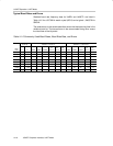
The results show the maximum per-bit error to be 5.08% of a BITCLK period.


