


CPU Registers
3-6 RISC 16-Bit CPU
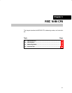
3.2.3 Status Register (SR)
The status register (SR/R2), used as a source or destination register, can be
used in the register mode only addressed with word instructions. The remain-
ing combinations of addressing modes are used to support the constant gen-
erator. Figure 3−6 shows the SR bits.
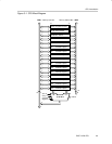
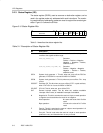
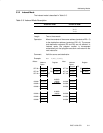
Figure 3−6. Status Register Bits
SCG0 GIE Z C
15 0
Reserved
N
CPU
OFF
OSC
OFF
SCG1V
879
Table 3−1 describes the status register bits.
Table 3−1.Description of Status Register Bits
Bit Description
V Overflow bit. This bit is set when the result of an arithmetic operation
overflows the signed-variable range.
ADD(.B),ADDC(.B) Set when:
Positive + Positive = Negative
Negative + Negative = Positive,
otherwise reset
SUB(.B),SUBC(.B),CMP(.B) Set when:
Positive − Negative = Negative
Negative − Positive = Positive,
otherwise reset
SCG1 System clock generator 1. This bit, when set, turns off the DCO dc
generator, if DCOCLK is not used for MCLK or SMCLK.
SCG0 System clock generator 0. This bit, when set, turns off the FLL+ loop
control
OSCOFF Oscillator Off. This bit, when set, turns off the LFXT1 crystal oscillator,
when LFXT1CLK is not use for MCLK or SMCLK
CPUOFF CPU off. This bit, when set, turns off the CPU.
GIE General interrupt enable. This bit, when set, enables maskable
interrupts. When reset, all maskable interrupts are disabled.
N Negative bit. This bit is set when the result of a byte or word operation
is negative and cleared when the result is not negative.
Word operation: N is set to the value of bit 15 of the
result
Byte operation: N is set to the value of bit 7 of the
result
Z Zero bit. This bit is set when the result of a byte or word operation is 0
and cleared when the result is not 0.
C
Carry bit. This bit is set when the result of a byte or word operation
produced a carry and cleared when no carry occurred.