


Scan IF Operation
24-33Scan IF
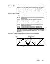
24.2.8 Quadrature Decoding
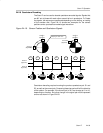
The Scan IF can be used to decode quadrature-encoded signals. Signals that
are 90° out of phase with each other are said to be in quadrature. To Create
the signals, two sensors are positioned depending on the slotting, or coating
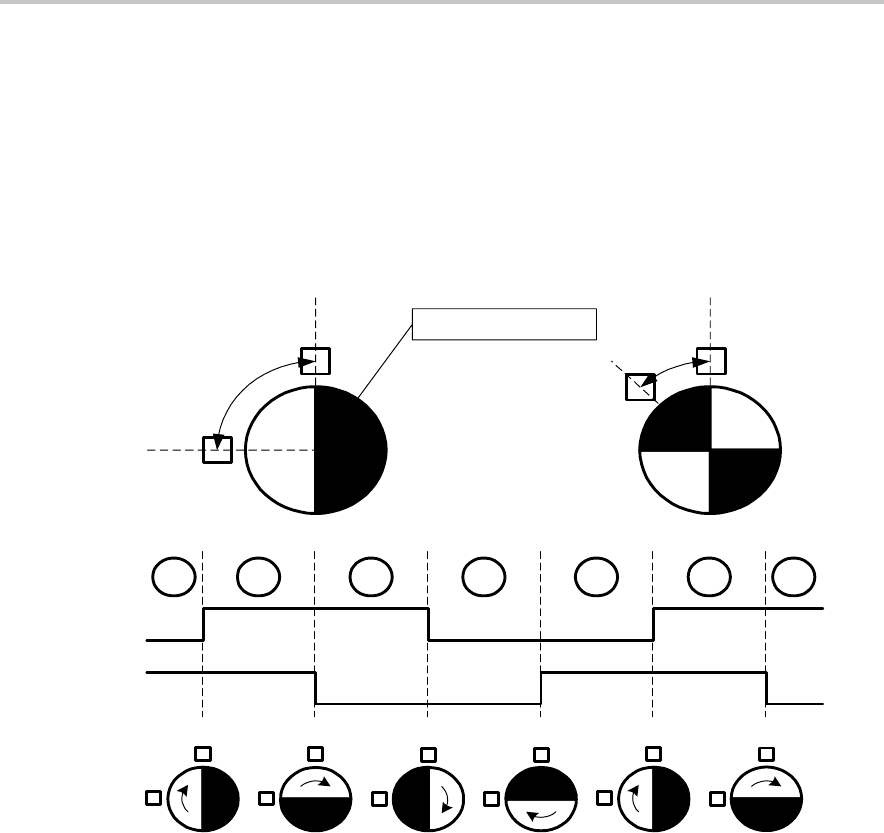
of the encoder disk. Figure 24−19 shows two examples for the sensor
positions and a quadrature-encoded signal waveform.
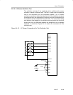
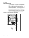
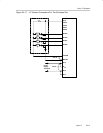
Figure 24−19. Sensor Position and Quadrature Signals
Sensor B
(Signal S2)
Sensor A
(Signal S1)
A
B
AAAA
BBBB
A
B
Sensor A
(Signal S1)
Sensor B
(Signal S2)
Sensor B
(Signal S2)
Sensor A
(Signal S1)
90
45
01 11 10 00 01 11 10
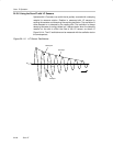
Damping or “dark” area.
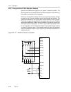
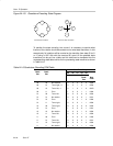
Quadrature decoding requires knowing the previous quadrature pair S1 and
S2, as well as the current pair. Comparing these two pairs will tell the direction
of the rotation. For example, if the current pair is 00 it can change to 01 or 10,
depending on direction. Any other change in the signal pair would represent
an error as shown in Figure 24−20.