


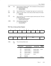

Timer_A Registers
12-23Timer_A
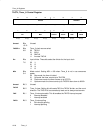
CCIE
Bit 4 Capture/compare interrupt enable. This bit enables the interrupt request of
the corresponding CCIFG flag.
0 Interrupt disabled
1 Interrupt enabled
CCI
Bit 3 Capture/compare input. The selected input signal can be read by this bit.
OUT
Bit 2 Output. For output mode 0, this bit directly controls the state of the output.
0 Output low
1 Output high
COV
Bit 1 Capture overflow. This bit indicates a capture overflow occurred. COV must
be reset with software.
0 No capture overflow occurred
1 Capture overflow occurred
CCIFG
Bit 0 Capture/compare interrupt flag
0 No interrupt pending
1 Interrupt pending
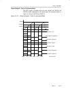
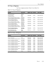
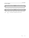
TAIV, Timer_A Interrupt Vector Register
15 14 13 12 11 10 9 8
0 0 0 0 0 0 0 0
r0 r0 r0 r0 r0 r0 r0 r0
76543210
0 0 0 0 TAIVx 0
r0 r0 r0 r0 r−(0) r−(0) r−(0) r0
TAIVx Bits
15-0
Timer_A Interrupt Vector value
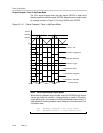
TAIV Contents Interrupt Source Interrupt Flag
Interrupt
Priority
00h No interrupt pending −
02h Capture/compare 1 TACCR1 CCIFG Highest
04h Capture/compare 2 TACCR2 CCIFG
06h Capture/compare 3
†
TACCR3 CCIFG
08h Capture/compare 4
†
TACCR4 CCIFG
0Ah Timer overflow TAIFG
0Ch Reserved −
0Eh Reserved − Lowest
†
Timer1_A5 only