


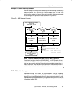
Operating Modes
2-13System Resets, Interrupts, and Operating Modes
2.3 Operating Modes
The MSP430 family is designed for ultralow-power applications and uses
different operating modes shown in Figure 2−9.
The operating modes take into account three different needs:
- Ultralow-power
- Speed and data throughput
- Minimization of individual peripheral current consumption
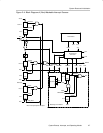
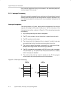
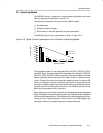
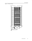
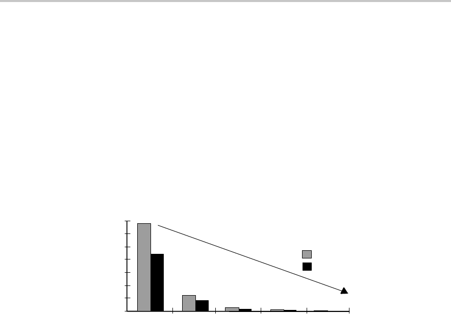
The MSP430 typical current consumption is shown in Figure 2−8.
Figure 2−8. Typical Current Consumption of 41x Devices vs Operating Modes
315
AM
300
270
225
180
135
90
45
0
LPM0 LPM2 LPM3 LPM4
200
55
32
17
11
0.9
0.7
0.1 0.1
V
CC
= 3 V
V
CC
= 2.2 V
Operating Modes
A @ 1 MHzµ
ICC/
The low-power modes 0−4 are configured with the CPUOFF, OSCOFF, SCG0,
and SCG1 bits in the status register The advantage of including the CPUOFF,
OSCOFF, SCG0, and SCG1 mode-control bits in the status register is that the
present operating mode is saved onto the stack during an interrupt service
routine. Program flow returns to the previous operating mode if the saved SR
value is not altered during the interrupt service routine. Program flow can be
returned to a different operating mode by manipulating the saved SR value on
the stack inside of the interrupt service routine. The mode-control bits and the
stack can be accessed with any instruction.
When setting any of the mode-control bits, the selected operating mode takes
effect immediately. Peripherals operating with any disabled clock are disabled
until the clock becomes active. The peripherals may also be disabled with their
individual control register settings. All I/O port pins and RAM/registers are
unchanged. Wake up is possible through all enabled interrupts.