Operating Modes
2-14 System Resets, Interrupts, and Operating Modes
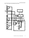
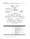
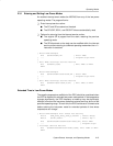
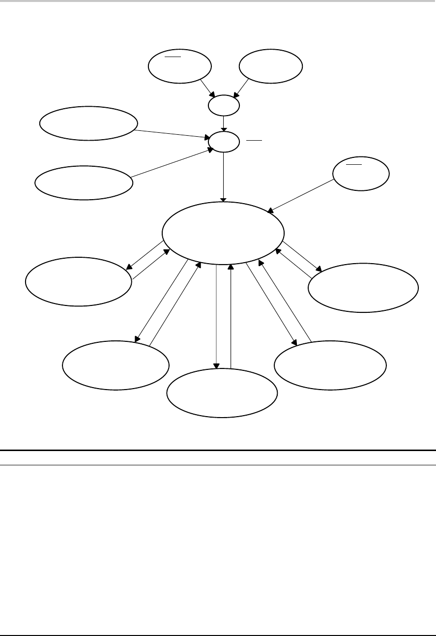
Figure 2−9. MSP430x4xx Operating Modes For Basic Clock System
Active Mode
CPU Is Active
Peripheral Modules Are Active
LPM0
CPU Off, FLL+ On,
MCLK On, ACLK On
CPUOFF = 1
SCG0 = 0
SCG1 = 0
CPUOFF = 1
SCG0 = 1
SCG1 = 0
LPM2
CPU Off, FLL+ Off,
MCLK Off, ACLK On
CPUOFF = 1
SCG0 = 0
SCG1 = 1
LPM3
CPU Off, FLL+ Off,
MCLK Off, ACLK On
DC Generator Off
LPM4
CPU Off, FLL+ Off,
MCLK Off, ACLK Off
DC Generator Off
CPUOFF = 1
OSCOFF = 1
SCG0 = 1
SCG1 = 1
RST/NMI
NMI Active
PUC
RST/NMI is Reset Pin
WDT is Active
POR
WDT Active,
Security Key Violation
WDT Active,
Time Expired, Overflow
WDTIFG = 1
WDTIFG = 1
RST/NMI
Reset Active
V
CC
On
WDTIFG = 0
LPM1
CPU Off, FLL+ Off,
MCLK On, ACLK On
CPUOFF = 1
SCG0 = 1
SCG1 = 1
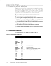
SCG1 SCG0 OSCOFF CPUOFF Mode CPU and Clocks Status
0 0 0 0 Active CPU is active, all enabled clocks are active
0 0 0 1 LPM0 CPU, MCLK are disabled
SMCLK , ACLK are active
0 1 0 1 LPM1 CPU, MCLK, DCO osc. are disabled
DC generator is disabled if the DCO is not used for
MCLK or SMCLK in active mode
SMCLK , ACLK are active
1 0 0 1 LPM2 CPU, MCLK, SMCLK, DCO osc. are disabled
DC generator remains enabled
ACLK is active
1 1 0 1 LPM3 CPU, MCLK, SMCLK, DCO osc. are disabled
DC generator disabled
ACLK is active
1
1 1 1 LPM4 CPU and all clocks disabled


