OA
16-5OA
16.2.4 OA Configurations
The OA can be configured for different amplifier functions with the OAFCx bits.
as listed in Table 16−1.
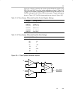
Table 16−1.OA Mode Select
OAFCx OA Mode
000 General-purpose opamp
001 Unity gain buffer
010 Reserved
011 Comparator
100 Non-inverting PGA amplifier
101 Reserved
110 Inverting PGA amplifier
111 Differential amplifier
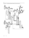
General Purpose Opamp Mode
In this mode the feedback resistor ladder is isolated from the OAx and the
OAxCTL0 bits define the signal routing. The OAx inputs are selected with the
OAPx and OANx bits. The OAx output is internally connected to the ADC12
input channel as selected by the OAxCTL0 bits.
Unity Gain Mode
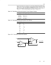
In this mode the output of the OAx is connected to R
BOTTOM
and the inverting
input of the OAx providing a unity gain buffer. The non-inverting input is
selected by the OAPx bits. The external connection for the inverting input is
disabled and the OANx bits are don’t care. The OAx output is internally
connected to the ADC12 input channel as selected by the OAxCTL0 bits.
Comparator Mode
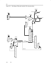
In this mode the output of the OAx is isolated from the resistor ladder. R
TOP
is connected to AV
SS
and R
BOTTOM
is connected to AV
CC
. The OAxTAP signal
is connected to the inverting input of the OAx providing a comparator with a
programmable threshold voltage selected by the OAFBRx bits. The
non-inverting input is selected by the OAPx bits. Hysteresis can be added by
an external positive feedback resistor. The external connection for the
inverting input is disabled and the OANx bits are don’t care. The OAx output
is internally connected to the ADC12 input channel as selected by the
OAxCTL0 bits.


