


SD16 Operation
21-5SD16
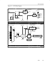
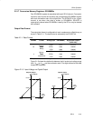
21.2.5 Channel Selection
Each SD16 channel can convert up to 8 differential pair inputs multiplexed into
the PGA. Up to six input pairs (A0-A5) are available externally on the device.
See the device-specific data sheet for analog input pin information. An internal
temperature sensor is available to each channel using the A6 multiplexer
input. Input A7 is a shorted connection between the + and - input pair and can
be used to calibrate the offset of each SD16 input stage.
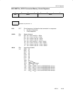
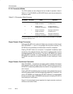
Analog Input Setup
The analog input of each channel is configured using the SD16INCTLx
register. These settings can be independently configured for each SD16
channel.
The SD16INCHx bits select one of eight differential input pairs of the analog
multiplexer. The gain for each PGA is selected by the SD16GAINx bits. A total
of six gain settings are available.
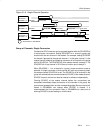
During conversion any modification to the SD16INCHx and SD16GAINx bits
will become effective with the next decimation step of the digital filter. After
these bits are modified, the next three conversions may be invalid due to the
settling time of the digital filter. This can be handled automatically with the
SD16INTDLYx bits. When SD16INTDLY = 00h, conversion interrupt requests
will not begin until the 4
th
conversion after a start condition.
Analog Input Characteristics
The SD16 uses a switched-capacitor input stage that appears as an
impedance to external circuitry. The equivalent impedance differs for the PGA
settings and is given in the device-specific datasheet.
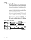
Anti-Aliasing Filter
An external RC anti-aliasing filter is recommended for the SD16 to prevent
aliasing of the input signal. The cutoff frequency should be < 10 kHz for a 1 Mhz
modulator clock and OSR = 256. The cutoff frequency may set to a lower
frequency for applications that have lower bandwidth requirements.