


Watchdog Timer Operation
10-5Watchdog Timer, Watchdog Timer+
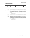
10.2.4 Watchdog Timer Interrupts
The WDT uses two bits in the SFRs for interrupt control.
- The WDT interrupt flag, WDTIFG, located in IFG1.0
- The WDT interrupt enable, WDTIE, located in IE1.0
When using the WDT in the watchdog mode, the WDTIFG flag sources a reset
vector interrupt. The WDTIFG can be used by the reset interrupt service
routine to determine if the watchdog caused the device to reset. If the flag is
set, then the watchdog timer initiated the reset condition either by timing out
or by a security key violation. If WDTIFG is cleared, the reset was caused by
a different source.
When using the WDT in interval timer mode, the WDTIFG flag is set after the
selected time interval and requests a WDT interval timer interrupt if the WDTIE
and the GIE bits are set. The interval timer interrupt vector is different from the
reset vector used in watchdog mode. In interval timer mode, the WDTIFG flag
is reset automatically when the interrupt is serviced, or can be reset with
software.
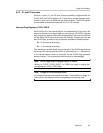
10.2.5 WDT+ Enhancements
The WDT+ module provides enhanced functionality over the WDT. The WDT+
provides a fail-safe clocking feature assuring the clock to the WDT+ cannot be
disabled while in watchdog mode. This means the low-power modes may be
affected by the choice for the WDT+ clock. For example, if ACLK is the WDT+
clock source, LPM4 will not be available, because the WDT+ will prevent
ACLK from being disabled. Also, if ACLK or SMCLK fail while sourcing the
WDT+, the WDT+ clock source is automatically switched to MCLK. In this
case, if MCLK is sourced from a crystal, and the crystal has failed, the FLL+
fail-safe feature will activate the DCO and use it as the source for MCLK.
When the WDT+ module is used in interval timer mode, there is no fail-safe
feature for the clock source.