Scan IF Operation
24-22 Scan IF
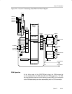
The current-state and next-state logic are reset while the Scan IF is disabled.
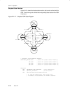
One of the bytes stored at addresses SIFPSMV to SIFPSMV + 3 will be loaded
first depending on the S1 and S2 signals when the Scan IF is enabled.
Signals S1 and S2 form a 2-bit offset added to the SIFPSMV contents to
determine the first byte loaded to the PSM output latch. For example, when S2
= 1, and S1 = 0, the first byte loaded by the PSM will be at the address
SIFPSMV + 2. The next byte and further subsequent bytes are determined by
the next state calculations and are calculated by the PSM based on the state
table contents and the values of signals S1 and S2.
Note: SIFSTOP(tsm) Signal Frequency
The SIFSTOP(tsm) signal frequency must be at least a factor of 32 lower
than the MCLK. Otherwise, unpredictable operation could occur.
Next State Calculation
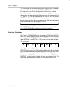
Bits 0, and 3 - 5 (Q0, Q3, Q4, Q5), and, if enabled by SIFQ6EN and SIFQ7EN,
bits 6 and 7 (Q6, Q7) are used together with the signals S1 and S2 to calculate
the next state. When SIFQ6EN = 1, Q6 is used in the next-state calculation.
When SIFQ6EN = 1 and SIFQ7EN = 1, Q7 is used in the next-state calculation.
The next state is:
Q7 Q6 Q5 Q4 Q3 Q0 S2 S1
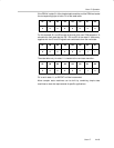
When Q7 = 0, the PSM state is updated by the falling edge of the
SIFSTOP(tsm) at the end of a TSM sequence. After updating the current state
the PSM moves the corresponding state table entry to the output latch. When
Q7 = 1, the next state is calculated immediately without waiting for the next
falling edge of SIFSTOP(tsm), regardless of the state of SIFQ6EN or
SIFQ7EN. The state is then updated with the next instruction fetch. The
worst-case time between state transitions in this case is 6 MCLK cycles.


