


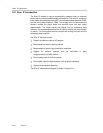

Scan IF Operation
24-6 Scan IF
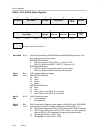
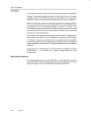
Excitation
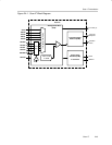
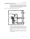
The excitation circuitry is used to excite the LC sensors or to power the resistor
dividers. The excitation circuitry is shown in Figure 24−3 for one LC sensor
connected. When the SIFTEN bit is set and the SIFSH bit is cleared the
excitation circuitry is enabled and the sample-and-hold circuitry is disabled.
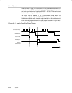
When the SIFEX(tsm) signal from the timing state machine is high the SIFCHx
input of the selected channel is connected to SIFV
SS
and the SIFCOM input
is connected to the mid-voltage generator to excite the sensor. The
SIFLCEN(tsm) signal must be high for excitation. While one channel is excited
and measured all other channels are automatically disabled. Only the selected
channel is excited and measured.
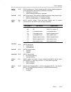
The excitation period should be long enough to overload the LC sensor slightly.
After excitation the SIFCHx input is released from ground when SIFEX(tsm)
= 0 and the LC sensor can oscillate freely. The oscillations will swing above
the positive supply but will be clipped by the protection diode to the positive
supply voltage plus one diode drop. This gives consistent maximum oscillation
amplitude.
At the end of the measurement the sensor should be damped by setting
SIFLCEN(tsm) = 0 to remove any residual energy before the next
measurement.
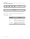
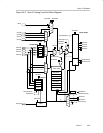
Mid-Voltage Generator
The mid-voltage generator is on when SIFVCC2 = 1 and allows the LC sensors
to oscillate freely. The mid-voltage generator requires a maximum of 6 ms to
settle and requires ACLK to be active and operating at 32768 Hz.