


RS232 PC-FAX EXPANDER Type 185 USER’S GUIDE
21
English
Switch 21 Outline
Digits 3 is not used for this product. Each has default of 0.
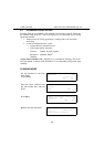
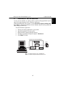
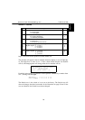
The switches will appear in the fax machine character display as rows of eight dig-
its. The digits have a value of 0 or 1. These values define what the fax machine
will do, and changing them will change what the fax machine will do.
Each digit in the display is referred to in the Operator’s Manual by a number from
0 to 7, starting from the
right
.
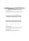
SWITCH 21 : 0 0 0 0 0 0 0 0
DIGIT NUMBER : 7 6 5 4 3 2 1 0
The Default row is the switch as it was set at the factory. The Switch row will
show the changes that have been made. In the illustration on page 20 and 21 the
rows are identical; the Switch has not been changed.
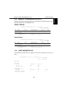
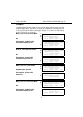
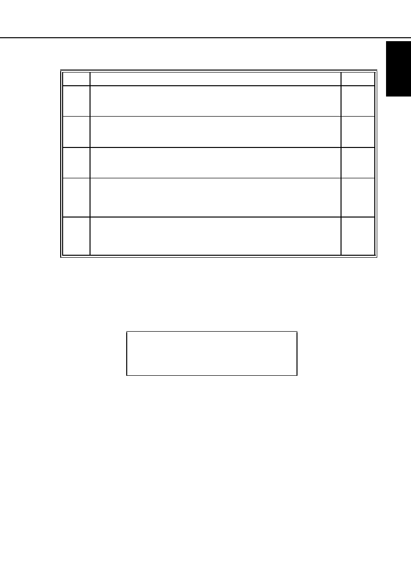
Digit Description Default
0
Reception
0 : Fax Reception
1 : PC Reception
0
1
PC Reception (when Digit 0 is 1)
0 : PC Direct Reception
1 : PC Memory Reception
0
2
Output Destination (when Digit 0 is 1 and Digit 1 is 1)
0 : Send to PC
1 : Print at Fax and send to PC
0
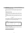
4
5
Image Density (Lighter) for scanning
Digits5, Digits4 (0, 1) Level 1
(1, 0) Level 2
(1, 1) Level 3
0
0
6
7
Image Density (Darker) for scanning
Digits7, Digits6 (0, 1) Level 5
(1, 0) Level 6
(1, 1) Level 7
0
0
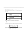
<User Parameters> Refer Op. Manual
SWITCH 21 Default:00000000
Current:00000000
↑Switch ↓Switch Cancel OK