Theory of Operation
3–24
1780R-Series Service Manual
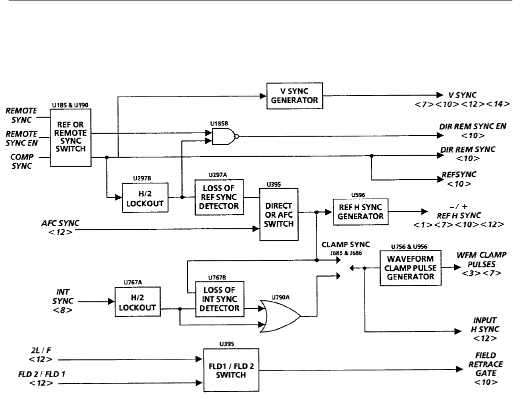
Diagram 9 H & V Sync Generators
The Horizontal and Vertical (line and field) Sync Generators extract the
synchronizing signals from the output of the Reference Sync Separator
(Diagram 8) or the Remote Sync Input to supply the required sync signals for the
rest of the instrument. In the absence of input video or remote sync, free-running
H and V sync signals are output to control sweep, clamps, and CRT readouts.
In addition to the synchronizing signals the Waveform Display Clamp Pulse
Generator is on this diagram. It provides correctly-timed clamp pulses to the four
signal inputs along with the Probe Input, during the active part of the video field
when the clamps are turned on.
Ref or Remote Sync Switch. U185A-C-D form a logic switch that selects between
the Remote Sync Input (from the rear-panel REMOTE connector) and Comp
Sync from the Reference Sync Separator (Diagram 8). If Remote Sync Enable is
high, U185A cannot AND, but U185D ANDs on Comp Sync. When the Remote
Sync Enable line is low, U185D cannot AND, but U185A ANDs on Remote
Sync. In either case one input of U185C will be high with the output of either
Overview
Circuit Theory


