Theory of Operation
3–60
1780R-Series Service Manual
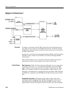
Diagram 21 Interconnect
All inputs to and outputs from the MPU circuit board are through the Intercon-
nect. There are two connectors on the MPU Interconnect, one that ties into the
1780R-Series main Interconnect circuit board, and one that serves as the I/O for
the MPU Annex board.
A transceiver is the bridge between the Internal Data (ID) Bus and External Data
(ED) Bus used by circuits not on the MPU circuit board (including the MPU
Annex board).
Three Internal Addresses (IA) are latched off the board and become External
Addresses (EA) used as control signals on four other circuit boards.
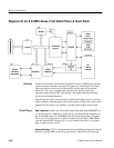
Data Transceiver. U105 is the I/O to the External Data Bus. It is a tri-state device
conducting A-to-B, B-to-A, or nonconducting depending on the /G and DIR
inputs. /G must be low for the transceiver to conduct in either direction. When
DIR is low it conducts from B-to-A and when high it conducts from A-to-B.
Direction of communication is controlled directly by the Master MPU (Diagram
16) /DDIN. It is enabled by the /EXTDBE from U305, the Interconnect Control
PAL.
Programmed Logic Array. U305 outputs clock signals, enables, and control
signals that augment the Internal Data (ID) Bus. Input signals to the array are
read (/RD) and write (/PERWR), Data Bus Enable (/DBE), and the six least
significant bits from the 24-bit Internal Address (IA) Bus. The Annex Data Bus
Overview
Circuit Theory


