Theory of Operation
3–114
1780R-Series Service Manual
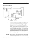
The primary side of the circuit is not referenced to chassis ground and typically,
the line common rides at – 150 volts, unless an isolation transformer is used. An
isolation transformer between the instrument and the mains power will let the
line side common float, which will allow the line side common to be connected
to ground.
WARNING. Troubleshooting or signal measurement should not be attempted
without an isolation transformer.
The power switch in this supply does not disconnect the mains power. Whenever
the instrument is plugged in, power line potential is available, and a neon
indicator, located on the fuse board, warns of this danger. The power switch is
electrically isolated from the line side circuitry for safety reasons. The coupling
medium in this case is the magnetic field in a transformer, enabling or disabling
a “Flea Power Oscillator.”
Line Rectifier and Filter. The rectifier diodes (CR100, CR101, CR102, and
CR103) are connected as a full-wave bridge when 220 volts mains is selected.
When 110 volts mains is selected, CR103 and CR101 are connected as a
full-wave doubler (CR102 and CR100 do not conduct). If 220 volts is applied
when S110 is in the 110 volt position, R210 and E210 cause the fuse to blow.
R210 is a fast acting varistor that keeps high voltage transients from triggering
the spark gap, E210. E210 can handle large currents to prevent an over-voltage
condition in the rest of the supply.
Filtering is accomplished with C160 and C170. High frequency energy is
prevented from entering the power line by a circuit consisting of C270, C271,
L370, C576, and C340, as well as the line filter located on the rear panel.
S250 is a thermal switch on the switching transistor heat sink. If the fan stops,
the switching transistor gets hot enough to trip the thermal switch (approximate-
ly 80° C).
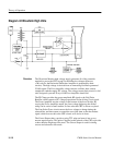
Switcher. Q250 is a high voltage transistor capable of withstanding 1000 volts
from collector to base. CR350, and CR351 and CR353 in the base circuit, are
wired as a Baker clamp, to keep Q250 from being driven into saturation and
enhancing the switching characteristics of the transistor. R150, in the emitter of
Q250, is a current sense resistor. Maximum peak voltage on the emitter is
2.2 volts, which corresponds to 4.3 amperes, including base drive current (which
is about 600 mA). Collector current is 3.7 amperes maximum (4.3 A minus
600 mA). Normally, the current levels are less, depending on power supply
loading.
Snubber. There are two snubber circuits, the voltage peak snubber and the rising
edge snubber. The voltage peak snubber consists of CR141, CR140, L140, L240,
Circuit Theory


