Theory of Operation
3–98
1780R-Series Service Manual
will not start quickly at sync pulse time to be synchronous with the sweep. An
LC Oscillator is used and calibrated to a crystal frequency reference during the
vertical interval.
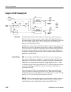
At Reference calibration time the Freq Cal Timer circuit generates a Frequency
Cal pulse that connects the Error Amplifier (U302A) output to the LC Oscillator
frequency determining Varactor diode. The change in capacitance caused by the
increase/decrease in voltage across the Varactor diode changes the LC Oscillator
frequency. The Error Amplifier voltage is stored away on a sample-and-hold cap
until the next calibration interval. In this way, the quick starting LC Oscillator is
always adjusted to the correct frequency.
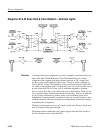
The output of the LC Oscillator is 10-MHz TTL pulses that clock a counter,
loaded to a predetermined starting count by data latched in from the Micropro-
cessor Data Bus. One of the two sets of latches is enabled (depending whether
Cursor 1 or Cursor 2 is selected) by the output of an enabling flip-flop. Ripple
out from the counter triggers a one-shot that generates the Ramp Start pulse used
by the analog delay to provide a ramp, which is compared to a DC level (from
the Master MPU) to output a timing cursor.
Cursor versus sweep synchronization determines when to draw the timing
cursors with respect to the horizontal sweep. A cursor shaper produces a very
narrow pulse from the leading edge of the timing cursor, and is located on the
waveform high voltage power supply.
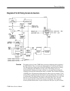
OSC. Q214 is a Colpitts LC Oscillator, with L115, C115, and C116 forming a
resonant tank circuit. CR214 is the Varactor diode, that changes capacitance to
provide frequency control for the oscillator. Q407 is the on-off switch for the
oscillator, which must be started and stopped with each delay count and each
time it is compared to the Reference Oscillator, Q100.
CR307, R307, and C214 form a quick start circuit, that causes the oscillator to
immediately begin oscillations when a falling edge is applied to the cathode of
CR307.
U207 is a voltage comparator that converts the sine-wave output of the LC
Oscillator to a TTL signal of the same frequency.
10 MHz Ref. Y105 is the resonant element in a Voltage-Controlled Crystal
Oscillator (VCXO), Q100, circuit. C109 is adjusted for 10 MHz at TP108.
Exclusive OR gate U202A is a buffer stage.
Phase Det. U202C (an Exclusive OR gate) and Q204 form a Phase Detector. The
voltage on the collector of Q204 is directly proportional to the phase difference
of the signals from the LC Oscillator and the 10 MHz Reference. This phase
difference signal is amplified in U302A, a frequency-dependent Error Amplifier.
Circuit Theory


