Adjustment Procedures
1780R-Series Service Manual
5–3
The <> switches below the Precision Measurement Control knob duplicate its
function, allowing a single increment of change per push.
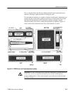
The instrument is made up of a number of etched circuit boards. Adjustments are
present on most of the boards, making it necessary to first find the circuit board
and then find the adjustment. This procedure contains a number of small
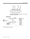
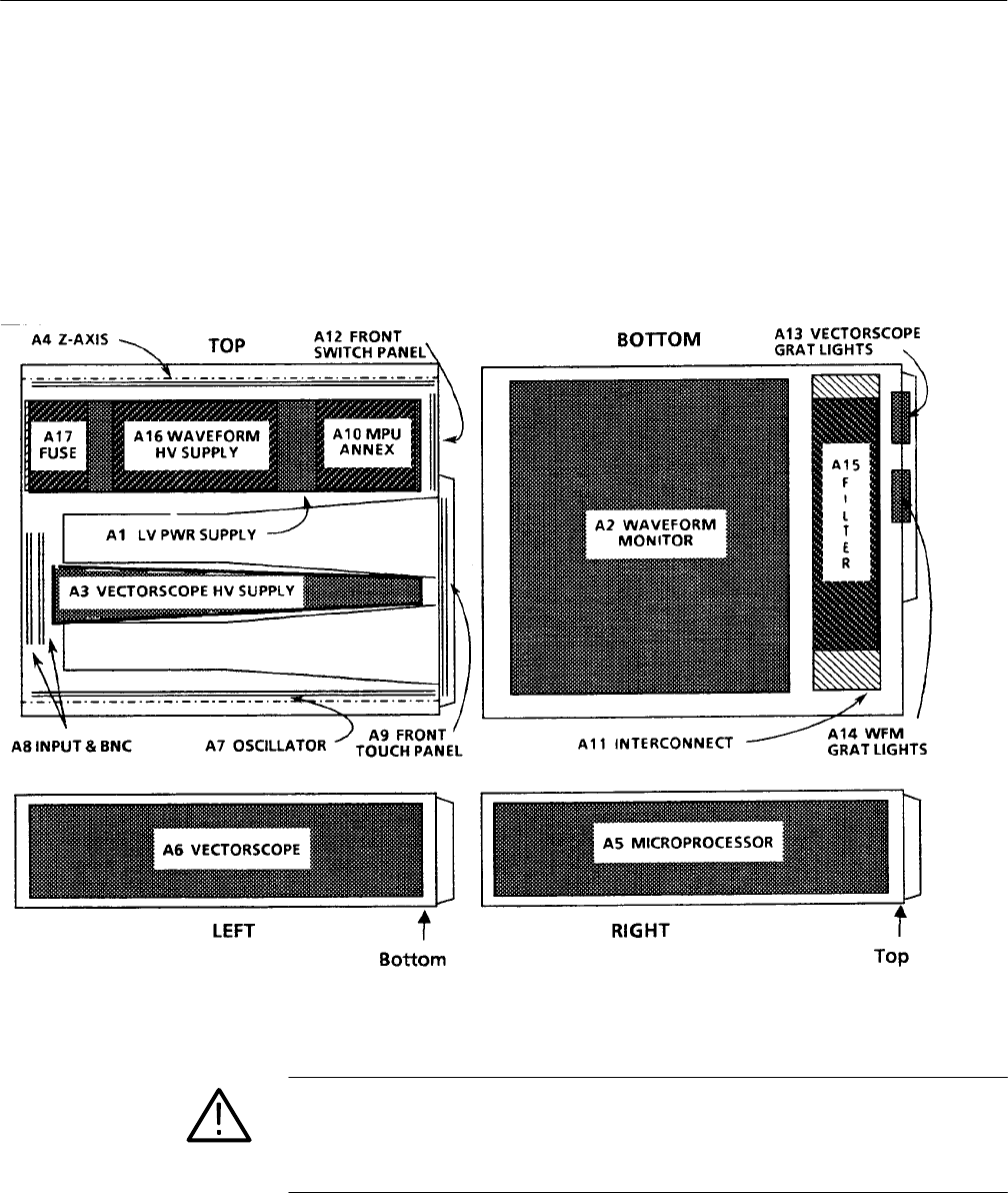
illustrations that can be used to locate the adjustments. In addition, Figure 5–3
shows where in the instrument each of the circuit boards is located.
Figure 5–3: 1780R-Series circuit board assembly locations
CAUTION. Use non-conducting tools to make the adjustments. If troubleshooting
is necessary, be sure to read the information given in the Troubleshooting
portion of Maintenance. This section includes a procedure for troubleshooting
the Power Supply.


