Corrective Maintenance
6–8
1780R-Series Service Manual
Use the following procedure to remove the instrument from the cabinet or case.
1. Check that the power cord is disconnected. Disconnect all the coaxial cables
from the rear-panel BNC connectors.
2. Remove the instrument from the rack mounting cabinet or from its portable
case. (Four 10–32 screws secure the instrument to the cabinet or portable
case. See Figure 2–8.)
Use the following procedure to remove the CRT.
WARNING. The CRT is a high vacuum device and must be handled with care.
Safety glasses, gloves, and protective clothing should always be worn when
handling CRTs.
1. To remove either CRT, use the Graticule Light Removal procedure to remove
the CRT Panel (located below the CRTs) and to loosen the bottom edge of
the CRT Frame Outer Bezel.
2. Disconnect the coaxial cable connector from J498 on the Vectorscope board
(A6). This cable comes from the front-panel PROBE BNC connector.
Disconnect the ribbon cable connector at J138 on the MPU Annex board
(A10).
3. Swing the bottom edge of the CRT Frame Outer Bezel outward until it
becomes unhinged at the top.
4. Remove the graticule light guides.
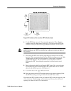
5. WAVEFORM CRT ONLY: Note the deflection lead colors (blue, brown,
green, red) and their connections to the CRT so they can be reconnected
properly later on. Disconnect the four deflection leads from the CRT. See
Figure 6–2.
Instrument Removal from
Rack Mounting Cabinet or
Portable Case
CRT Removal


