Adjustment Procedures
1780R-Series Service Manual
5–41
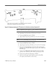
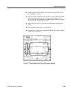
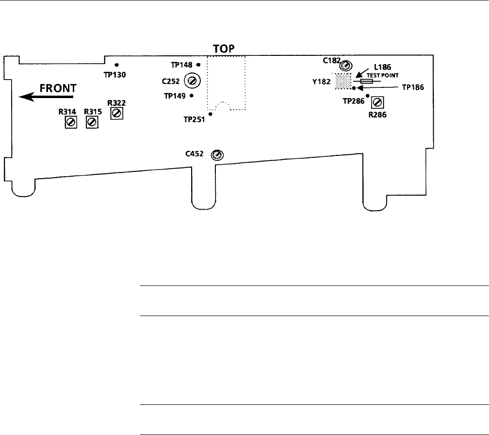
Variable resistors are shown rotated 90_ from the way they are mounted on the assembly;
variable resistors are adjustable from the top of the circuit board.
Figure 5–16: Adjustment and test point (TP) locations for the Oscillator circuit board (Assembly A7).
NOTE. The adjustments given in parts d., f., and h. should not be adjusted if the
voltages at the test points are within tolerance.
d. Adjust Burst Lock Center Freq (A7C182) for 2.0 V ±2.0 V.
e. Connect the DMM Volts lead to A7TP149.
f. Adjust +Delta F Center Freq (A7C252) for 3 V to 8 V (5 V nominal).
NOTE. For access to adjustments A7C252 and A7C452, the Oscillator board
(A7) must be mounted on the Board Extender Bracket.
g. Connect the DMM Volts lead to A7TP251.
h. Adjust Output Center Freq (A7C452) for +3 V to +8 V (+5 V nominal).
i. Disconnect the Digital Multimeter and the Color Bar signal from the
instrument. Leave the Black Burst signal connected to the 1780R-Series
EXT REF input.
j. Connect a second Black Burst signal from the television test signal
generator to the 1780R-Series CH A INPUT and terminate in 75 W.
k. Connect a test oscilloscope 10X probe to A7TP186.
l. Set the test oscilloscope vertical amplifier controls to 50 mV/Div,
AC-coupled; set the Time/ Div control to 20 ms.


