Installation
1780R-Series Service Manual
2–11
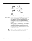
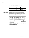
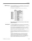
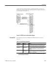
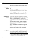
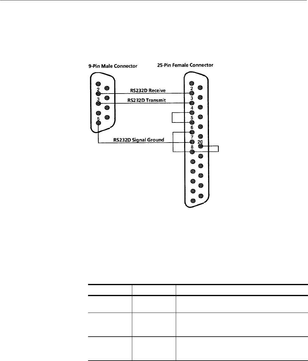
(of the 9-pin male connector) and pin 7 (of the 25-pin female connector). In
addition, pins 4 and 5 and pins 6, 8, and 20 of the 25-pin connector will need to
be wired together. See Figure 2–6.
Figure 2–6: RS232D serial interface adapter diagram
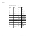
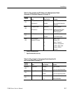
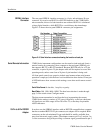
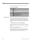
The command set for the the 1780R-Series SERIAL interface is shown in
Table 2–6.
Table 2–6: Serial Remote Commands
Command* Function Results
#U or #u UPLOAD 1780R-Series sends a stream of data, representing the
current instrument configuration, to the host computer.
#D or #d DOWNLOAD 1780R-Series expects a stream of data representing an
instrument configuration of the same form that was
uploaded.
#P or #p PARTIAL
DOWNLOAD
1780R-Series expects a stream of data representing an
instrument configuration, with the knob settings (focus,
intensity, etc.) not affected.
* The # character indicates a remote control command. All transmissions are ignored
until this character is received.
Command Set


