Troubleshooting Procedures
6–28
1780R-Series Service Manual
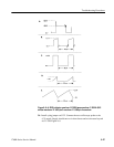
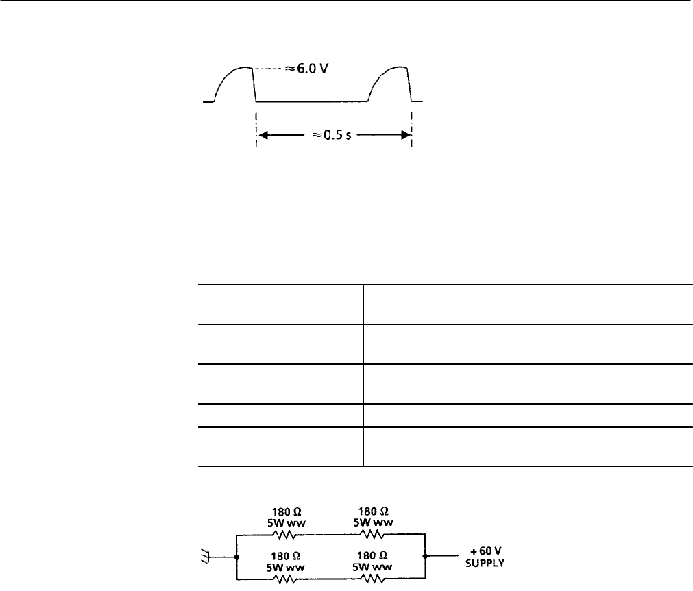
Figure 6–9: +5 V supply output waveform when over voltage protection is operating
Current Limit Adjustment (A1R466)
Variable Auto Transformer: See Equipment Required List in the Adjustment Procedures
section.
Television Test Signal Genera-
tor (Optional):
Color Bars. See Adjustment Procedures.
75 W Feed-Through Termina-
tor.
See Adjustment Procedures.
75 W Coaxial Cable. See Adjustment Procedures.
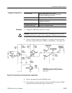
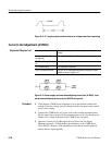
180 W 10W Resistive Load: Use four 180 W, 5W wirewound resistors connected in series
parallel as shown in Figure 6–10.
Figure 6–10: Power supply load used when adjusting current limit (A1R466). Load
can be connected between the top end of A2L638 and ground
1. Verify that the 1780R-Series instrument is set to the desired nominal line
voltage. If the line voltage must be changed, set the rear-panel mains switch
to the correct setting.
2. Connect the 1780R-Series AC power cord to the variable autotransformer.
Set the mains Power switch for the autotransformer to On. Set the autotrans-
former to the voltage indicated on the 1780R-Series rear panel.
3. Optional: Connect a Color Bar signal from a Television Test Signal
Generator, through a 75 W feed-through terminator, to the 1780R-Series
CH A INPUT connector. (The instrument can be checked and/or adjusted
without the test signal applied.)
Equipment Required List
Procedure


