Troubleshooting
6–16
1780R-Series Service Manual
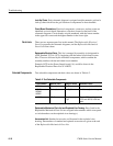
Look Up Charts. Each schematic diagram is assigned an alpha-numeric grid and a
look-up chart which lists the grid location of components on that schematic.
Circuit Board Illustrations. Electrical components, connectors, and test points are
identified on circuit board illustrations, which are located on the back of the
schematic diagrams. Circuit boards are grid numbered, with the lowest number
in the upper left corner and the highest number in the lower right.
There are two separate parts lists in this manual. The Replaceable Electrical
Parts List precedes the schematic diagrams, and the Replaceable Mechanical
Parts List follows them.
Replaceable Electrical Parts. This list is arranged by assembly (as designated in
ANSI Standard Y32.16–1975), beginning with the etched circuit board assem-
blies. These are followed by the individual components, which combine the
assembly number with the individual circuit number.
Example: R570 on the Power Supply board (A1) would be shown in the
Replaceable Electrical Parts List as A1R570.
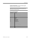
Test selectable components and their values are shown in Table 6–2.
Table 6–2: Test Selectable Components
Circuit Number Nominal Value Range of Values Selection Criteria
A2C918 Not Installed 2.2 pF Increase bandwidth of AUX IN
A6C171
A6C848
A6C851
Not Installed 0 – 20 pF Insufficient adjustment range
A16C300 .47 mF .22 mF
.1 mF
To set +160V supply between
157V and 180V at +160V test
point.
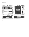
Replaceable Mechanical Parts List and Exploded View Drawing. Parts listed in the
Replaceable Mechanical Parts List are assigned index numbers which correspond
to circled numbers on the exploded view drawing(s).
Accessories List. Standard accessories are illustrated in the exploded view
drawing. Part numbers of standard and optional accessories are given at the end
of the Replaceable Mechanical Parts List.
Parts Lists
Selected Components


