Performance Verification
1780R-Series Service Manual
4–11
NOTE. Leave the 1780R-Series internal jumpers in their factory-set positions
unless directed otherwise. The factory-set positions are listed in Section 2,
Installation, Electrical.
Install the metal cover on the instrument and leave it installed when following
this procedure to check performance requirements.
H Verify that the 1780R-Series instrument is set to the desired nominal line
voltage as indicated on the rear panel. If the line voltage must be changed,
set the rear-panel mains switch to the other setting.
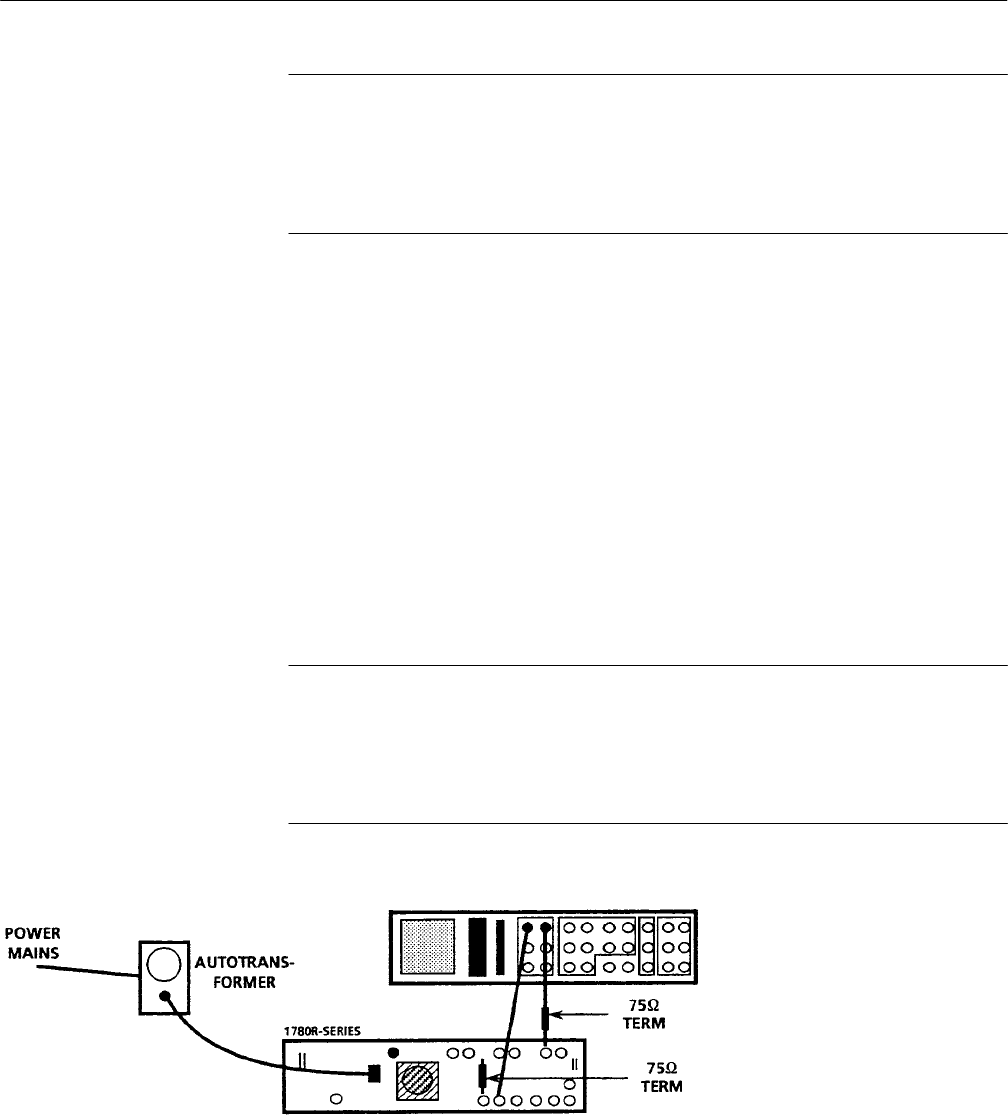
H Connect the 1780R-Series AC power cord to the variable autotransformer.
Set the mains Power switch for the autotransformer to On. Set the autotrans-
former to the voltage indicated on the 1780R-Series rear-panel.
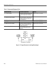
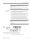
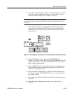
H Connect a Television Test Signal Generator Color Bar signal through a 75 W
feed-through termination to the 1780R-Series CH A INPUT connector.
H Connect the Television Test Signal Generator Black Burst signal to the
1780R-Series EXT REF connector. Connect a 75 W end-line termination to
the remaining side of the EXT REF loop-through connector. See Figure 4–5.
NOTE. Leave the Black Burst signal connected to the EXT REF connector
throughout the entire Performance Check Procedure except when directed
otherwise.
Once the instrument is powered up, allow at least 20 minutes of warm-up time
before continuing.
Figure 4–5: Initial equipment hook-up for the Performance Check Procedure
H Set the 1780R-Series instrument POWER switch to ON.
Preliminary Setup


