Theory of Operation
1780R-Series Service Manual
3–57
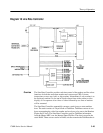
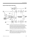
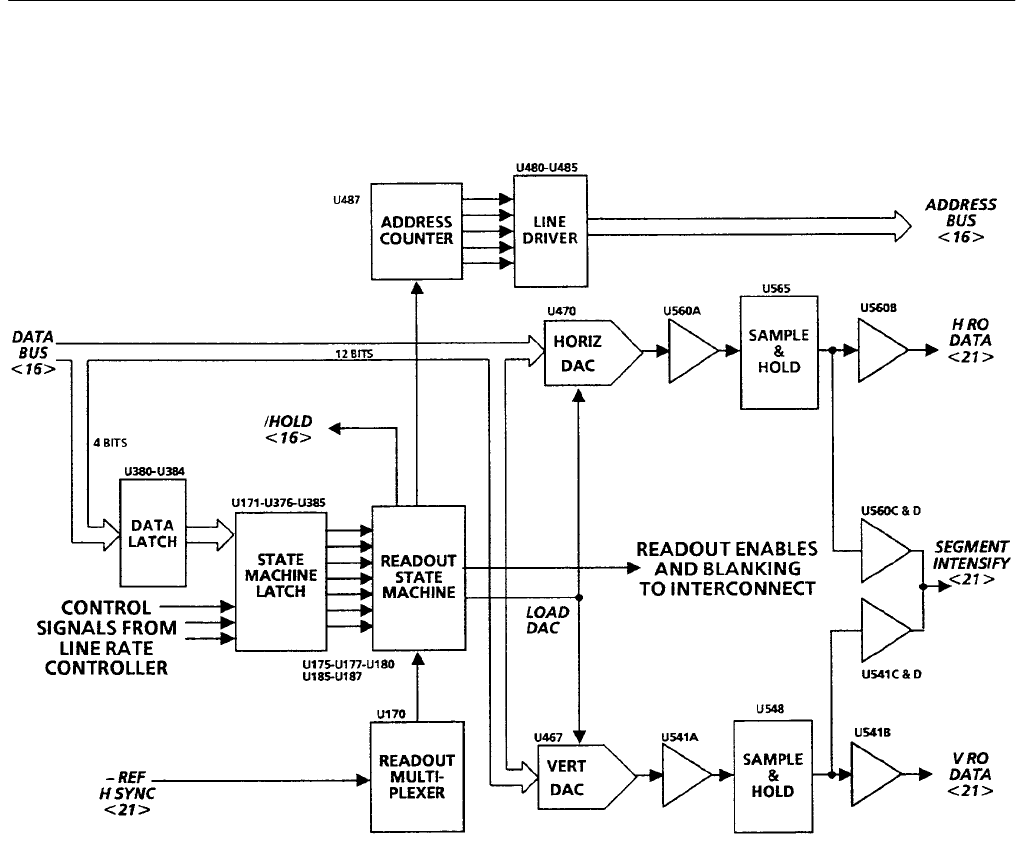
Diagram 20 Readout Engine & Read Output
The asynchronous Readout Engine outputs the readout characters that are
displayed on the vectorscope and waveform monitor CRTs. Digital data from the
Dynamic RAM is converted to an analog output for display. The D/A Converters
are loaded from the Internal Data (ID) Bus and output the analog signal to
sample-and-hold circuits for display on the CRTs. The heart of the Readout
Engine is a state machine made up of five PALs. State machine operation is
controlled by the 4 most significant bits (MSBs) from the Internal Data (ID) Bus,
and control signals generated by the Line Rate Controller, Diagram 18.
Data Latch. The 4 MSBs of data from the Dynamic Random Access Memory
(DRAM) are input to a Data Latch consisting of U380 and U384 (positive edge
triggered D-type flip-flops). U380 and U384 are individually triggered by the
/Latch 1 and /Latch 2 outputs from the DRAM (Diagram 17). /Latch 1 is used
for vertical readout; /Latch 2 for horizontal readout.
Overview
Circuit Theory


