Theory of Operation
1780R-Series Service Manual
3–89
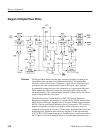
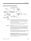
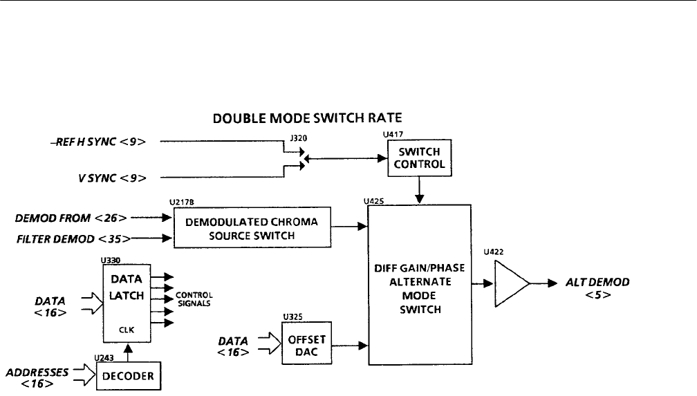
Diagram 34 Diff Gain/Phase Alt Mode Switch
The 1780R-Series offers a choice of either single display mode or a double
display mode that can be nulled. The Alternate, or double mode, is switched
about itself to display a mirror image. Sources of chroma for the mode switch are
either directly from the Demodulators or a Recursive Filtered Demodulator
output when noise needs to be reduced.
In addition, this diagram contains the Data Latch and Address Decoder used to
write data from the Master MPU to the Oscillator circuit board.
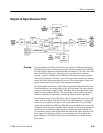
Switch Control. Output switching is controlled by U417, a dual D-type flip-flop.
Switching rate is selectable between Field/2 or Line/4, depending on the location
of the plug on J320. The Line/4, which is used with a PAL-modulated ramp
signal, divides the –Ref H sync by 2 in U417A to clock U417B for an additional
divide by 2. The Field/2 uses V sync to clock U417B only for the divide by 2.
Factory-programmed position is Line/4.
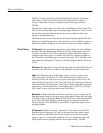
When dP measurements are made, the phase of the subcarrier signal is varied and
measured. But when dG is measured, the fixed chroma level from the demodula-
tors is compared to a DC offset level and the offset level measured.
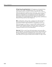
Demodulated Chroma Source Switch. U217 is a set of analog switches, controlled
by the Microprocessor, used to select a filtered or unfiltered demod output signal
for the Alternate Mode switch, U425. Q322 is a common emitter amplifier,
whose gain is approximately 1, serving as an inverting buffer that sets the input
DC level for the Alternate Mode switch.
Overview
Circuit Theory


