Theory of Operation
1780R-Series Service Manual
3–117
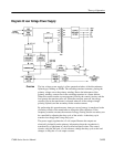
Output Filters. The filters are all the standard pi configuration except the –8 volt
filter. There are three powdered iron beads (L420, L421, and L422) on the
+5 volt secondary wires to help raise the other output voltages to the proper
values.
Error Amp. U131 is a shunt regulator supplying a +5 volt reference. The reference
pin is the negative input to an internal amplifier and the cathode is the output.
The reference input is set internally to operate 2.5 volts above the anode, which
is grounded.
Jumper J122 is to test the over-voltage protection circuit by increasing the
+5 volt reference to +6.5 volts.
U120 is the Error Amp, which compares the +5 volt reference to the +5 volt
output, and drives the Opto-Isolator, U230, with the difference signal.
Over-voltage Protection. Q220 is a silicon-controlled rectifier (SCR). If the gate is
pulled a diode drop higher than the cathode, the device fires and shorts the
+5 volt supply to ground. VR220 causes Q220 to fire if the +5 volt supply rises
above about 6 volts.
Power Switch Oscillator. The primary winding of T130 is the resonant element in
the Power Switch Oscillator. When the power switch is closed (power on), a
100W resistive load is placed across the secondary of the transformer, disabling
the oscillator.
When the Power Switch Oscillator is running (power off), it provides pulses of
base current to Q130. Q130 supplies current through CR370 that pulls pin 3 of
U460 high and prevents operation of the power supply.
The Power Switch Oscillator operates in short bursts, as dictated by U460, which
powers the oscillator. C132 prevents the supply from starting on the transitions
that occur when U460 becomes active before the oscillator has started.


