Operating Information
1780R-Series Service Manual
2–29
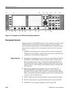
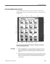
7. VERT POS. Positions the selected display up and down. Positioning range
depends on the display selected; range is much greater for the waveform
monitor displays than it is for the vectorscope displays.
8. HORIZ POS. Positions the selected display left and right. Positioning range
depends on the display selected; range is much greater for the waveform
monitor displays than it is for the vectorscope displays.
9. PRESET. Lighted momentary contact switch that turns on or off a list of
preset front-panel setups that the operator can program and select for
repeated measurements.
10. MEASURE. Lighted momentary contact switch that brings up menu
selections for factory pre-programmed measurement setups.
11. CONFIGURE. Lighted momentary contact switch that calls up menus to
guide the configuring of the measurement criteria, such as clamping,
coupling, etc.
12. CALIBRATE. Lighted momentary contact switch that brings up a menu to
provide calibration adjustments and signal choices for instrument calibration.
13. TIME CURSORS. A single momentary contact on/off switch enabling the
timing cursors, which use the Precision Measurement knob, or the <>
buttons. Time Cursors switch has a built-in indicator.
14. VOLTAGE CURSORS. A single momentary contact on/off switch enabling
the voltage cursors, which use the Precision Measurement knob, or the <>
buttons. Voltage Cursors switch has a built-in indicator.
15. PHASE SHIFT. A single momentary contact on/off switch enabling the
precision phase shift measurements, which use the Precision Measurement
knob, or the <> buttons. Phase Shift switch has a built-in indicator.
16. LINE SELECT. A single momentary contact on/off switch enabling the line
select function, which displays the selected line (first in a multiple line
display, or brightened in a field display). Alpha-numeric readout indicates
the selected line and field on the waveform monitor CRT. Line Select switch
has a built-in indicator. Selection of the exact line and field is accomplished
through the Precision Measurement knob, or the <> buttons.
17. REFERENCE SET. Used with the Phase Shift mode to store a reference
phase. REFERENCE SET is used in the VOLTAGE CURSORS mode when
RELATIVE is selected. It is also used in the LINE SELECT mode to access
line 19 in the vertical interval.
18. Knob. The Precision Measurement control operates with the four functions
selected by the preceding switches. Provides continuously adjustable range
to the selected measurement.
Special Purpose Switches
Precision Measurement
Controls


