Adjustment Procedures
5–22
1780R-Series Service Manual
d. Press the CALIBRATE button to exit the menu.
13. Adjust Picture Monitor
a. Set 1780R-Series INPUT selection to CH A.
b. Select the LEFT DISPLAY-PIX mode.
c. Adjust Pix Vert Position (A6R407), Pix Vert Gain (A6R404), Pix Horiz
Gain (A6R604), and Pix Horiz Pos (A6R606) for a slightly under-
scanned picture monitor display. (There should be a narrow black border
about 1/16-inch to 1/8-inch or 1.5 mm to 3 mm at the edges of the
display.)
d. Select the LEFT DISPLAY-VECT mode.
e. Disconnect the Color Bar signal from the CH A INPUT connector.
14. Adjust Calibrator Amplitude
a. Check that no signal is applied to the 1780R-Series CH A INPUT.
Check that Black Burst is applied to the EXT REF.
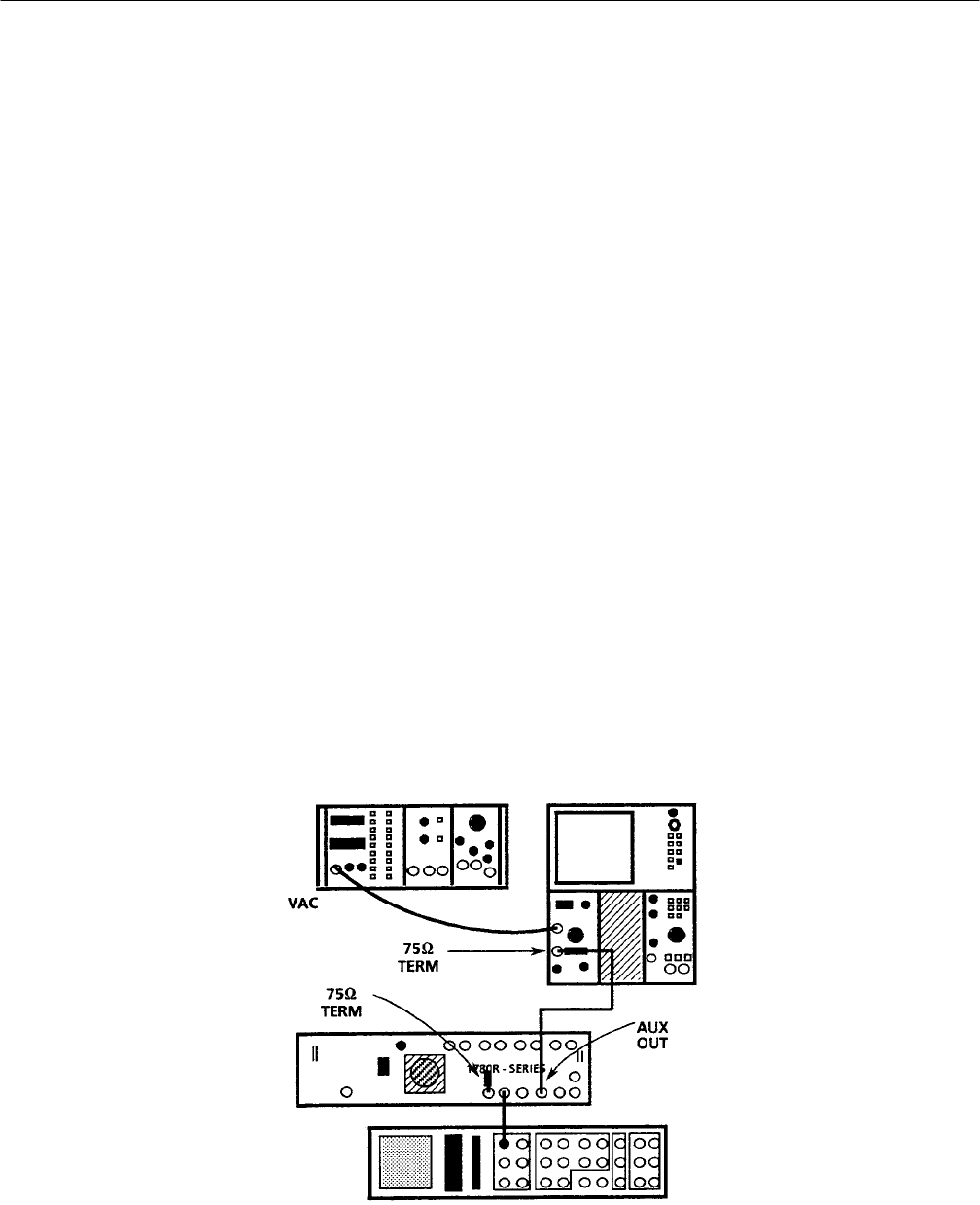
b. Connect the output of the Video Amplitude Calibrator (VAC) to the
+Input of the test oscilloscope Differential Comparator.
c. Connect a 75 W coaxial cable to the 1780R-Series AUX OUT. Connect
the other end of the cable, through a precision (0.2%) 75 W feed-through
termination, to the –Input of the test oscilloscope Differential Com-
parator. See Fig. 5–12.
Figure 5–12: Connections for adjusting the calibrator amplitude
