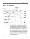
Theory of Operation
1780R-Series Service Manual
3–81
provide a TTL pulse at F
SC
to the Digital Phase Shifter and the comparison input
of the Mixer stage.
The External CW loop-through input is buffered, to common mode out ground
currents, and bandpass filtered. The filtered output is converted to TTL pulses,
for the Digital Phase Shifter, by a strobe-controlled complementary comparator.
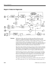
Buffer and Bandpass Filter, and Mixer and Low-Pass Filter. Q297 and Q298 form a
non-inverting buffer amplifier. W198 makes the input to the buffer single ended,
but in extreme conditions can be removed for common mode input, to reduce
hum current on the Ref Video coaxial cable run. The output of the buffer is
bandpass filtered (value of C392 depends on the frequency of F
SC
, NTSC, or
PAL color standard).
The Mixer, U193, is an MC1496P balanced demodulator with the bandpass
filtered Ref Video input to the + and – signal inputs. TTL pulses from the
VCXO, ÷4 flip-flop, are input to the + Carrier Input; – Carrier is tied to digital
ground through R293 to set a comparison point. Stage gain is set by R189 and
the balance adjustment is R286. The output of U193 drives a 300-kHz, low-pass,
pi-filter consisting of C187, L186, and C285. R184 is the filter’s load resistor.
Sampling Transconductance Amplifier and VCXO. U179 is a transconductance
operational amplifier, with a sampling input at pin 5. It is connected as an
integrating Error Amplifier. Pulses from the Pulse Generator change the loop
characteristics, by altering amplifier gain, from wide bandwidth for the unlocked
or capture mode to narrow band for phase lock. The narrow bandwidth integrates
out noise and burst phase errors on a line-by-line basis.
Q275 is a Voltage-Controlled Crystal Oscillator, running at 4 × F
SC
. Y182 is a
14.318 MHz crystal for NTSC color standard, or 17.73448 MHz for the PAL
color standard. C182 is a trimmer capacitor adjusted for a signal amplitude of
2 volts. Q169 turns off the VCXO for NTSC External CW operation; it is
inoperative for PAL External CW operation.
U171 is a 2-stage 4 counter made up of D-type flip-flops that is clocked at 4F
SC
by the collector of Q275. The counter provides TTL output pulses (+F
SC
and
–F
SC
) to the Input Switch, U469. In addition, a clock-cycle delayed+F
SC
output
is fed back to the Mixer to complete the phase-lock loop.
Envelope Detector and Pulse Gating. Q390, which is driven by bandpass filtered
Ref Video, is an emitter follower buffer stage driving an envelope detector to
provide a high to U376A when chrominance is present on the Ref Video input.
U376B is a delay one-shot that delays Reference Sync (Ref Sync) for proper
phasing. Q372 is a half-shot circuit that provides a window during backporch of
the Ref Sync. U376A is wired to use its AND gate input (pins 1 and 2) as a
coincidence detector that will start the one-shot only if chrominance (burst) is
Circuit Theory


