Theory of Operation
1780R-Series Service Manual
3–95
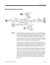
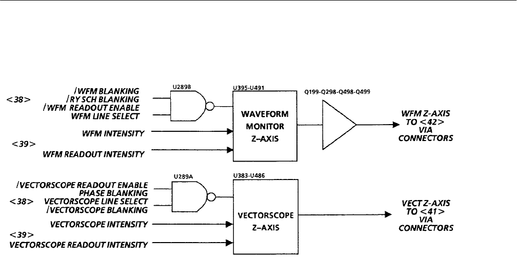
Diagram 36 Z-Axis
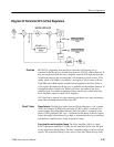
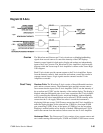
The Waveform and Vectorscope Z-Axis circuits act on blanking/unblanking
signals from several sources to control the intensity of the CRT displays.
Intensity control signals for both active display and readout are independently
input to the Z-Axis circuits. The Waveform Z-Axis Amplifier is shown on this
diagram, while the Vectorscope Z-Axis Amplifier is shown on the Vector High
Volts diagram.
Both Z-Axis circuits provide current outputs to the Z-Axis Amplifiers. Inputs
from the Intensity controls, both waveform and readout, control the current in
separate current sources. Logic signals steer the currents into the Z-Axis
Amplifiers as needed.
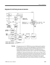
Waveform Z-Axis. The Waveform Z-Axis consists of three differential transistor
pairs and two current sources. The differential pairs and their current sources
steer current into the input of the Z-Axis Amplifier. U491C sets the intensity of
the waveform and U395C sets the intensity of the readout display. The display is
blanked when the differential pairs do not steer current into the Z-Axis Amplifi-
er. By controlling the differential pairs, waveform blanking, readout blanking,
and field rate line select intensification can be effected. U491D normally steers
current into the 5 volt supply. When line select is on and the instrument is
displaying field rate sweeps, U491D steers current into the Z-Axis Amplifier to
make the display brighter for the selected line. U289B is a four-input NAND
gate controlling U395D. If any of the inputs of U289B go low, the waveform
blanking is enabled and the active display is blanked. Differential pair U395A
and B steer current from the readout current source into the Z-Axis Amplifier.
Vectorscope Z-Axis. The Vectorscope Z-Axis consists of two current sources and
two current steering differential pairs, U383D and U486D. U383D steers current
Overview
Circuit Theory


