Installation
2–8
1780R-Series Service Manual
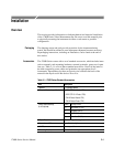
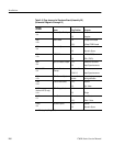
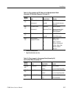
Table 2–5: Plug Jumpers for Vectorscope Board (Assembly A6)
and Oscillator Board (Assembly A7) (Cont.)
Jumper
Number
PurposePlug PositionName
J320 (A7)
<34>
Diff Phase Display 1-2 {
2-3
Double (H)/4
Single (V)/2
{
Factory installed position.
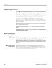
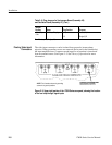
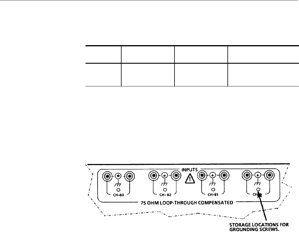
The video input connectors can be isolated from ground to increase hum
rejection. When grounding screws are removed (and stored in the blank holes)
the input amplifiers have a common mode input for ac hum that is introduced
from an external source. See Figure 2–3. See Theory of Operation for more
information.
NOTE: The illustration shows the grounding
screws in the ground positions.
Figure 2–3: Upper right portion of the 1780R-Series rear panel, showing the location
of the four loop-through signal inputs
Floating Video Input
Connectors


