Adjustment Procedures
1780R-Series Service Manual
5–33
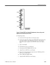
c. Select the following 1780R-Series settings: INPUT A-B1, WAVEFORM
HORIZONTAL-ONE-FIELD, and WAVEFORM GAIN-X5-On.
NOTE. Do not turn the CMR adjustments given in parts d., g., and j. of this step
if chrominance nulls within 14 IRE for NTSC (100 mV for PAL).
d. Adjust B1 CMR (A2C1329, A2R1333) for best nulled display.
Chrominance should be nulled within 14 IRE for NTSC (100 mV for
PAL).
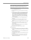
e. Move the dual-input coupler from CH A INPUT to CH B2 INPUT.
f. Select the B1-B2 INPUT mode.
g. Adjust B2 CMR (A2C1232, A2R1221) to obtain a nulled display.
Chrominance should be nulled within 14 IRE for NTSC (100 mV for
PAL).
h. Move the dual-input coupler from CH B2 to CH B3 INPUT.
i. Select the B1-B3 INPUT mode.
j. Adjust B3 CMR (A2C1131, A2R1135) for a nulled display. Chromi-
nance should be nulled within 14 IRE for NTSC (100 mV for PAL).
k. Select the following mode: INPUT-CH B1 and WAVEFORM
GAIN-X5-Off.
l. Disconnect the Multiburst signal and dual input coupler.
24. Adjust CH B1 Input Frequency Response
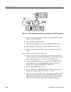
a. Connect the leveled sine wave generator output, through a 50 W-to-75 W
minimum loss attenuator, to the CH B1 INPUT connector. Do not
terminate the loop-through connector.
b. Connect a peak-to-peak detector head to the other CH B1 INPUT
connector. Connect a coaxial cable from the detector head to the +Input
on the peak-to-peak detector amplifier.
c. Connect the peak-to-peak detector amplifier output to the input of a
DMM.
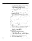
d. Check that a 75 W termination is connected to the 1780R-Series PIX
MON OUT connector. Set the WFM HORIZONTAL to TWO-LINE and
check that INPUT-CH B1 is selected.
e. Set the generator frequency to 50 kHz (reference). Check that the
1780R-Series INPUT selection is set to CH B1. Set the generator output


