Theory of Operation
3–40
1780R-Series Service Manual
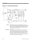
Logic and Timing to control the oscillator is generated, based upon the burst-
sync relationship of reference video. Also, field identification information is
provided to the MPU for line select.
Finally, the burst-sync relationship of the reference video is determined. The
Burst Phase Detector is part of the Reference Sync circuitry on Diagram 8.
Sync 50% Detector. Q1451, Q1548, and Q1450 form an inverting amplifier with a
gain of 8. R1451 and R1448 determine the AC gain. U1455 and U1460
(sample-and-holds) sample the amplifier output at backporch and sync tip time.
A resistive divider (R1552-R1558) derives a voltage halfway between the
backporch and sync tip. This 50% level is stored on C1550. Q1551 (an emitter
follower) buffers the voltage and feeds it to the amplifier input through R1450.
This sets the 50% sync point at the amplifier output, which is approximately
+3 volts.
Q1548, in the operational amplifier, saturates when the amplifier output drops
below 0 volts. This saturated condition, coupled with the clamp feedback, is used
to strip off large amplitude video that would otherwise break down the compara-
tor.
U1357, Q1358, and Q1359 form a high-gain, low-offset comparator. Inverted
video from the Clamped Amplifier is input through pin 2 of U1357D. A
precision resistive divider consisting of R1556 and R1557 sets a DC level on the
other comparator input that is a voltage corresponding to a point halfway
between backporch and sync tip. R1455 nulls the input offset so that the
comparator switches at the 50% sync point regardless of small sync height
variations. R1458 and C1364 provide AC hysteresis. The comparator output is a
positive-going, 5 volts transition at U1357B (pin 11) when the 50% point on the
leading edge sync is reached.
Timing for the backporch and sync tip sample-and-holds (U1455 and U1460) is
provided by a Sync Separator driving a Pulse Generator state machine, U1097.
The Pulse Generator is a 9-bit subcarrier rate counter that is triggered by internal
sync. It counts up until it reaches a terminal count, and then resets to wait for the
next internal sync. U996 outputs 7 bits of the counter. U1097 outputs bits 8 and
9, the counter reset, and the decoding to make the sample pulses. All three
sample pulses are nominally 3 s wide; the SYNC GATE pulse (pin 16) straddles
the leading sync edge, /BP SAMP (pin 14) and /ST SAMP (pin 15) occur during
backporch and sync tip time. A /VERT LOCKOUT pulse, from the SCH Phase
and Timing (Diagram 14), is input to pin 19 of U1097 to inhibit backporch and
sync tip sampling during the vertical interval.
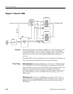
SCH Sync Locked Oscillator. Q1092, C1091, and C1094 form a Colpitts oscillator
that is series tuned by crystal Y1190 and varactor CR1288. C1194 is adjusted so
that the oscillator runs at 4 × F
SC
when there is 5.5 volts on the varactor.
Circuit Theory
(Diagram 15)


