Theory of Operation
1780R-Series Service Manual
3–65
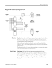
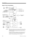
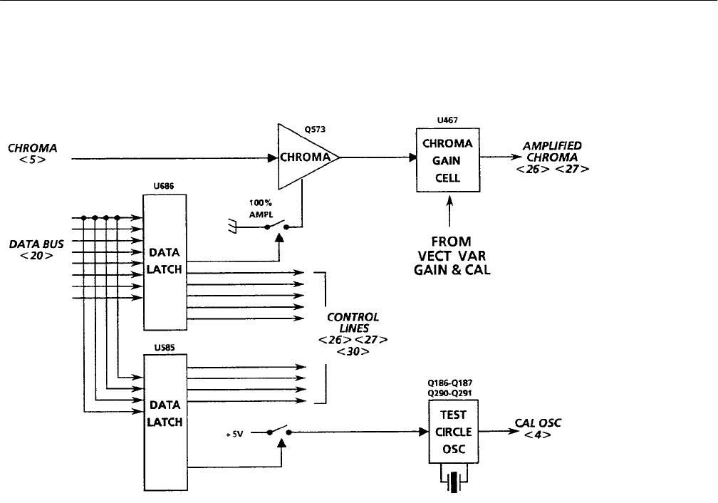
Diagram 25 Vectorscope Input & Gain
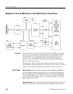
The Data Latches decode the Vectorscope operating instructions from the Master
MPU. Two of the circuits controlled by these instructions, Chroma Amp and
Test Circle Oscillator, appear on this schematic. The Test Circle Oscillator is a
crystal-controlled oscillator running at F
SC
.
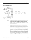
When the Chroma Amplifier is switched in, gain in the Chroma Gain Cell is
reduced by 25% to allow 100% amplitude color bar excursions to fall within the
graticule targets.
The Vectorscope Gain Cell controls chroma amplitude in response to the setting
of the Vector Gain Cal and Vector Variable Gain.
Data Latches. U585 and U686 are rising edge triggered, multiple D-type
flip-flops, with negative clear, operating as data latches. Data, from the Micro-
processor, is applied to the D inputs of both flip-flops and clocked through on a
rising clock transition to be held until either a new Clock or a Clear (from the
Master MPU) occurs. U585 has complementary outputs making it possible to
generate high or low asserting control signals for the associated Vectorscope
circuitry.
Overview
Circuit Theory


