Adjustment Procedures
1780R-Series Service Manual
5–17
d. Set the 1780R-Series front-panel SCALE and INTENSITY controls for
normal brightness.
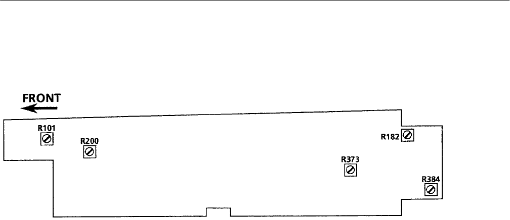
Figure 5–8: Adjustment locations on the Vectorscope HV Supply circuit board (Assembly A3)
7. Adjust Vector Astigmatism and Focus
a. Set the front-panel FOCUS control to midrange between “beeps.”
b. Adjust Focus (A3R182) and Astigmatism (A3R200) for a well-defined
vector display. See Figure 5–8.
8. Adjust Readout Character Symmetry and DAC Gain
a. Set the 1780R-Series INPUT selection to CH B1 for no-signal input.
b. Press the CONFIGURE button to On. Select COUPLING-GND on
PAGE 1 of the menu displayed on the Vectorscope CRT.
c. Adjust Horiz Shape (A5R536) and Vert Shape (A5R555) for best readout
character symmetry as displayed on the Vectorscope CRT. (A5 is the
Microprocessor circuit board. See Figure 5–9.)
d. Press the button below the Waveform CRT.
