Adjustment Procedures
5–48
1780R-Series Service Manual
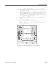
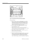
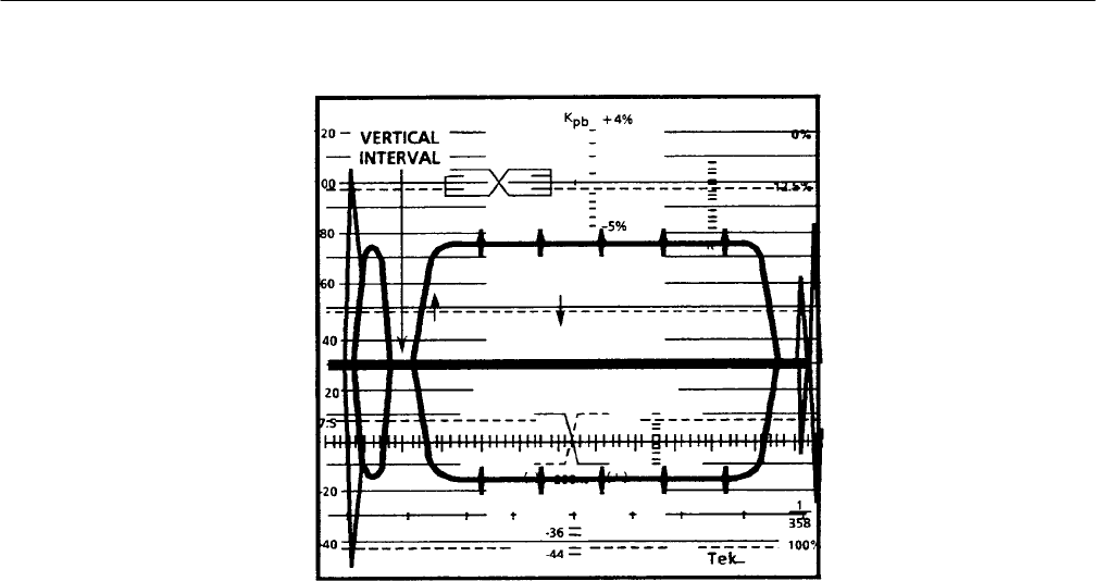
Figure 5–18: Noise Reduction-OFF. Demod offset properly adjusted
38. Adjust SCH Phase
a. Connect a Color Bar signal from a TEKTRONIX TSG-170A NTSC
Television Generator to the 1780R CH A INPUT connector. Connect a
75 W end-line termination to the remaining CH A INPUT connector.
Connect the generator Black Burst signal to the EXT REF connector.
Check that the EXT REF loop-through connector is terminated into
75 W. (Use a TSG-271 PAL Generator for the 1781R.)
b. Select the 1780R-Series LEFT DISPLAY-SCH mode of operation.
Check that REF-EXT is selected.
c. Connect a 10X probe from the test oscilloscope vertical input to
A2TP1170. Set the test oscilloscope vertical deflection factor to 2 V/Div,
Input Coupling to DC, and the sweep rate to 2 ms/Div.
d. Adjust VCO Adj (A2C1072) for a DC level between 6 V and 8 V (7 V
nominal) on the test oscilloscope CRT.
e. Disconnect the 10X probe from A2TP1170.
f. Connect a coaxial cable from the generator Frame/Ref connector to Ch 1
of the test oscilloscope dual trace amplifier. Connect a 10X probe from
Ch 2 of the dual-trace amplifier to A2TP981. Set test oscilloscope
vertical deflection factors to 5 V and mode to Chopped. Set the time
base to 10 ms/Div and trigger on the Field 1 Reference (Ch 1) signal. Use


