Theory of Operation
3–84
1780R-Series Service Manual
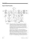
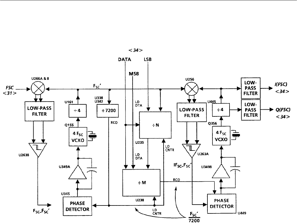
Diagram 32 Digital Phase Shifter
The Digital Phase Shifter uses the input subcarrier frequency to generate an
intermediate and somewhat lower subcarrier frequency. The intermediate
subcarrier, which is divided into 7200 parts, is used to load a Microprocessor-
generated count into a programmable counter. The ripple output from the
programmable counter then provides a reference for a regenerated subcarrier,
which reflects the difference between the front-panel phase offset and the
incoming reference. The resultant output subcarrier is then used by the Vector-
scope to demodulate the color signal.
The subcarrier source is either the F
SC
or EXT CW from the Subcarrier
Regenerator schematic. Incoming F
SC
is mixed with the VCXO-generated F
SC
’,
which derives a difference frequency that is low-pass filtered at approximately
500 Hz. The low-pass filtered difference signal is converted to TTL levels by a
balanced comparator and used as one input to a Phase Detector, where it is
compared to the output of a divide by 7200 counter. Resultant signal drives an
Integrating Error Amplifier that controls the frequency of the approximately
4F
SC
VCXO. VCXO output frequency is divided down by four to produce F
SC
’
that is input to one side of the input Mixer to close the input phase-lock loop.
Overview


