Theory of Operation
1780R-Series Service Manual
3–87
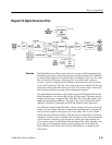
Diagram 33 Horizontal AFC & Post Regulators
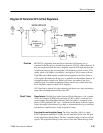
REF SYNC, originating from the H Sync Generator on Diagram <9>, is
compared to the H rate sync divided down from the VCO by a Phase Detector. If
they are not phase locked, the Error Amplifier output will be high and cause the
Acquisition Sweep to run and sweep the VCO frequency control circuits. VCO
output, which is at 8 MHz, is divided by 2 and again by 256 to return to H rate.
Eight MHz and 4 MHz signals are buffered and supplied to the Noise Filter as
clock signals. Divided down H rate sync is applied to the Input Phase Detector to
complete the phase-locked loop. When lock occurs, the output of the Error
Amplifier goes low and the Acquisition Sweep does not run, which allows the
Error Amplifier output to control VCO frequency.
AFC Sync Out is delayed for correct phasing with direct sync, thus preventing a
jump when switching between Direct and AFC.
Phase Detector. The Ref Sync input, from the H Sync Generator, is AC-coupled
(C303) and clamped (CR303) into one input of U407, which is connected as a
current output, Integrating Phase Detector. Ref Sync phase is compared to the
phase of VCO-generated AFC sync. A difference in the phase of the two signals
causes the output of the detector to go high, to indicate that the loop is unlocked,
and the Error Amplifier turns on the Acquisition Sweep.
Error Amplifier and Acquisition Sweep. The Error Amplifier (U415) is a dual
bi-FET operational amplifier. U415B is the AC path and U415A is the DC path
for the Acquisition Sweep Ramp. The Error Amplifier output is the sum of both
signals. The Acquisition Sweep occurs once for each line. When the loop locks
Overview
Circuit Theory


